System and method for deadlock-free routing on arbitrary network topologies

a topology and deadlock-free technology, applied in the field of data routing through a communications network, can solve problems such as inability to forward received data, congestion of links near the root of the spanning tree, and network deadlock, so as to avoid deadlock and avoid deadlock

Active Publication Date: 2006-01-31
ORACLE INT CORP
View PDF10 Cites 8 Cited by
  • Summary
  • Abstract
  • Description
  • Claims
  • Application Information

AI Technical Summary

Benefits of technology

[0015]The disclosed system then performs a shortest-path route calculation with the following constraint: starting at any given layer, for each node, proceed to calculate a shortest path to every other node in the graph where at any node being utilized to assess a given minimum path, the path may move to any higher-ordered layer, but may never return to a lower ordered layer. In this way, within each layer, a path moves through a tree and thus avoids deadlock. Between layers, a path may move only in a single direction, thus also avoiding deadlock.

Problems solved by technology

However, even where loop-free paths have been determined, traffic flows can interact with each other to cause a problem known as “deadlock” within the network.
Each of the switches in such a group may be unable to forward its received data because the switch to which that data must be forwarded has no available buffers to store the data.
A significant problem with up / down routing is that links near the root of the spanning tree get congested and become bottlenecks leading to lower throughput.

Method used


Image

  • System and method for deadlock-free routing on arbitrary network topologies
  • System and method for deadlock-free routing on arbitrary network topologies
  • System and method for deadlock-free routing on arbitrary network topologies

Examples


Embodiment Construction

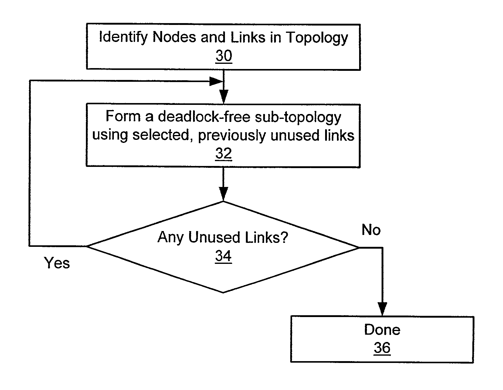
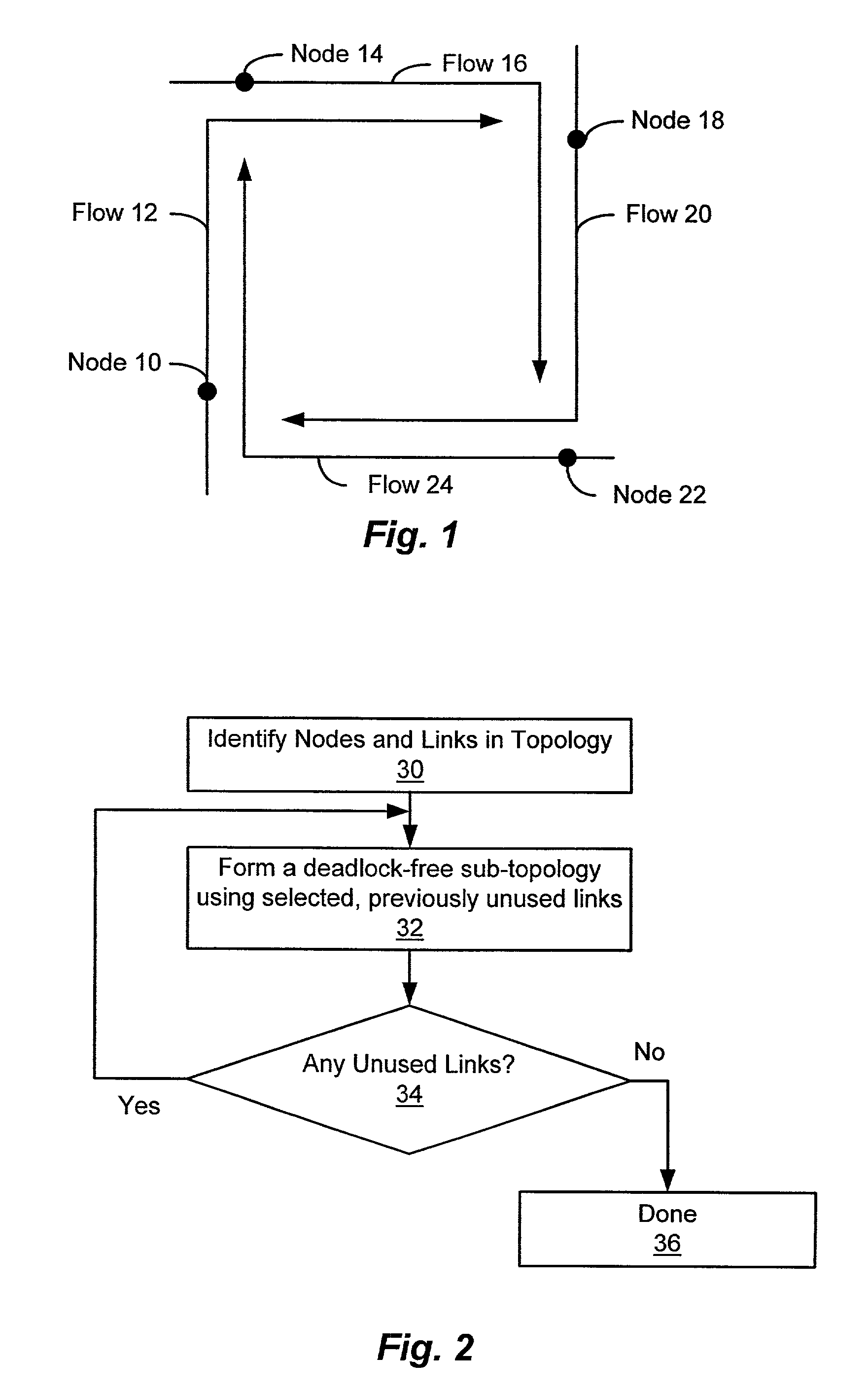
[0026]The disclosed system generates an ordered set of deadlock-free sub-topologies of a network in order to find a deadlock-free set of paths through the network. The deadlock-free sub-topologies generated by the disclosed system are referred to herein as “layers”. As shown in FIG. 2, at step 30, the disclosed system first identifies those nodes and links that form the network to be processed. The nodes of the network may, for example, consist of various internetworking devices, such as those devices conventionally referred to as switches. The links of the network may consist of any type of communications link suitable for interconnecting the nodes of the network.

[0027]At step 32 of FIG. 2, the disclosed system forms a layer consisting of a deadlock-free sub-topology of the network being processed. The layer formed at step 32 may be any kind of deadlock-free sub-topology of the network. The links used to form a layer during step 32 are considered to be “used”, and therefore unavail...


PUM


Abstract

A system and method for calculating a deadlock-free free set of paths in a network generates an ordered set of deadlock-free sub-topologies, referred to as “layers.” The ordered set of layers is then used to determine a deadlock-free set of paths through the network by performing a shortest-path route calculation with the following constraint: starting at any given layer, for each node, proceed to calculate a shortest path to every other node in the graph where, at any node being utilized to assess a given minimum path, the path may move to any higher-ordered layer, but may not return to a lower-ordered layer.

Description

CROSS REFERENCE TO RELATED APPLICATIONS[0001]N / ASTATEMENT REGARDING FEDERALLY SPONSORED RESEARCH OR DEVELOPMENT[0002]N / ABACKGROUND OF THE INVENTION[0003]The present invention relates generally to routing of data through a communications network, and more specifically to a system and method for calculating deadlock-free sets of paths for passing information over a communication network.[0004]As it is generally known, routing is the process of determining the nodes through which a data unit is forwarded along its path between a source and a destination within a network. The route taken by data, such as a packet or other specific type of data unit, is also referred to herein as the path taken between the source and destination. Routing is performed by various kinds of data forwarding devices, including routers and switches. A forwarding device that performs routing is typically connected to multiple communication links, and operates to select at least one of those communication links a...

Claims


Application Information

Patent Timeline
Patent Type & Authority Patents(United States)
IPC IPC(8): H04L12/26H04L12/56
CPCH04L45/12H04L45/42H04L45/18
Inventor REYNDERS, JOHN V.PERLMAN, RADIA J.STEELE, JR., GUY L.
Owner ORACLE INT CORP
Why Eureka
Try Eureka