
Method and apparatus of modulating the filtering of radiation during radiographic imaging

a radiographic imaging and radiation filtering technology, applied in the field of diagnostic imaging, can solve the problems of increasing the overall manufacturing cost of the imaging system, unable to consider each individual patient, etc., and achieve the effect of reducing radiation exposur

Inactive Publication Date: 2006-01-31
GENERAL ELECTRIC CO
View PDF6 Cites 11 Cited by
  • Summary
  • Abstract
  • Description
  • Claims
  • Application Information

AI Technical Summary

Benefits of technology

This approach reduces radiation exposure to sensitive areas while maintaining image quality, eliminating the need for multiple filters and lowering manufacturing costs by dynamically adjusting the attenuation profile based on the subject's anatomy.

Problems solved by technology

However, fashioning an imaging system with a sufficient number of bowtie filters to accommodate the idiosyncrasies encountered during scanning of numerous patients can be problematic in that each individual patient cannot be contemplated.
Additionally, manufacturing an imaging system with a multitude of bowtie filters increases the overall manufacturing cost of the imaging system.

Method used


Image

  • Method and apparatus of modulating the filtering of radiation during radiographic imaging
  • Method and apparatus of modulating the filtering of radiation during radiographic imaging
  • Method and apparatus of modulating the filtering of radiation during radiographic imaging

Examples


Embodiment Construction

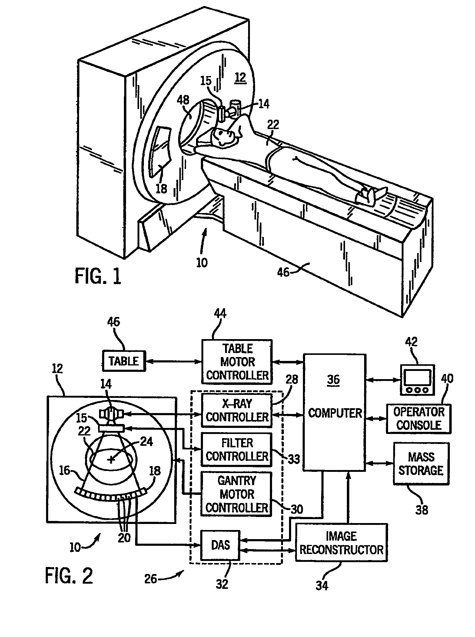
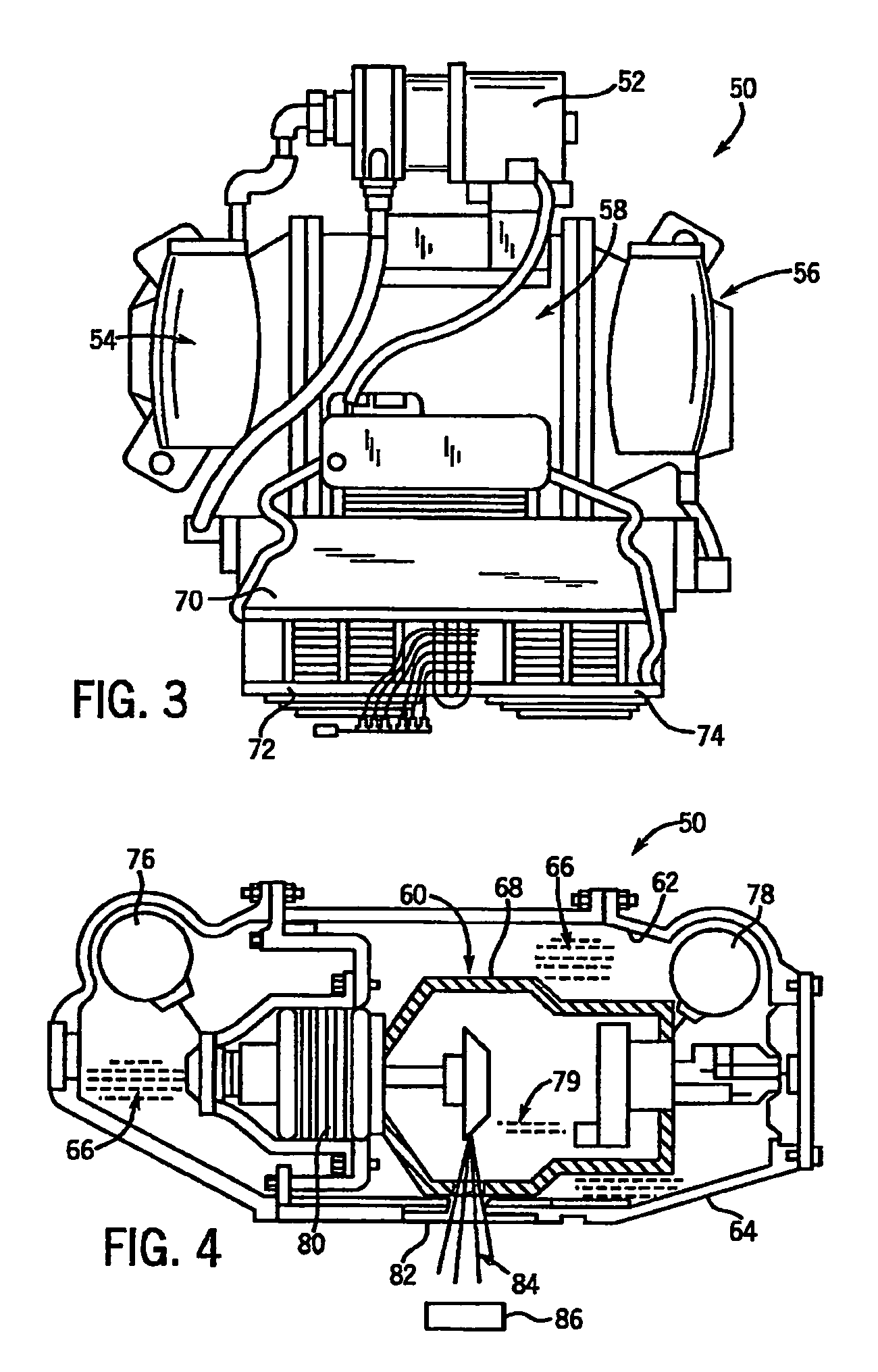
[0037]The present invention is described with respect to a radiographic imaging system such as the CT system shown in FIGS. 1–2 and the x-ray system shown in FIGS. 3–4. However, it will be appreciated by those skilled in the art that the present invention is equally applicable for use with other radiographic imaging systems. Moreover, the present invention will be described with respect to the emission and detection of x-rays. However, one skilled in the art will further appreciate, that the present invention is equally applicable for the emission and detection of other high frequency electromagnetic energy.

[0038]Referring to FIGS. 1 and 2, a “third generationCT imaging system 10 is shown as including a gantry 12. The present invention, however, is applicable with other CT systems. Gantry 12 has an x-ray source 14 that projects a beam of x-rays 16 through filter 15 toward a detector array 18 on the opposite side of the gantry 12. Detector array 18 is formed by a plurality of detec...


PUM


Abstract

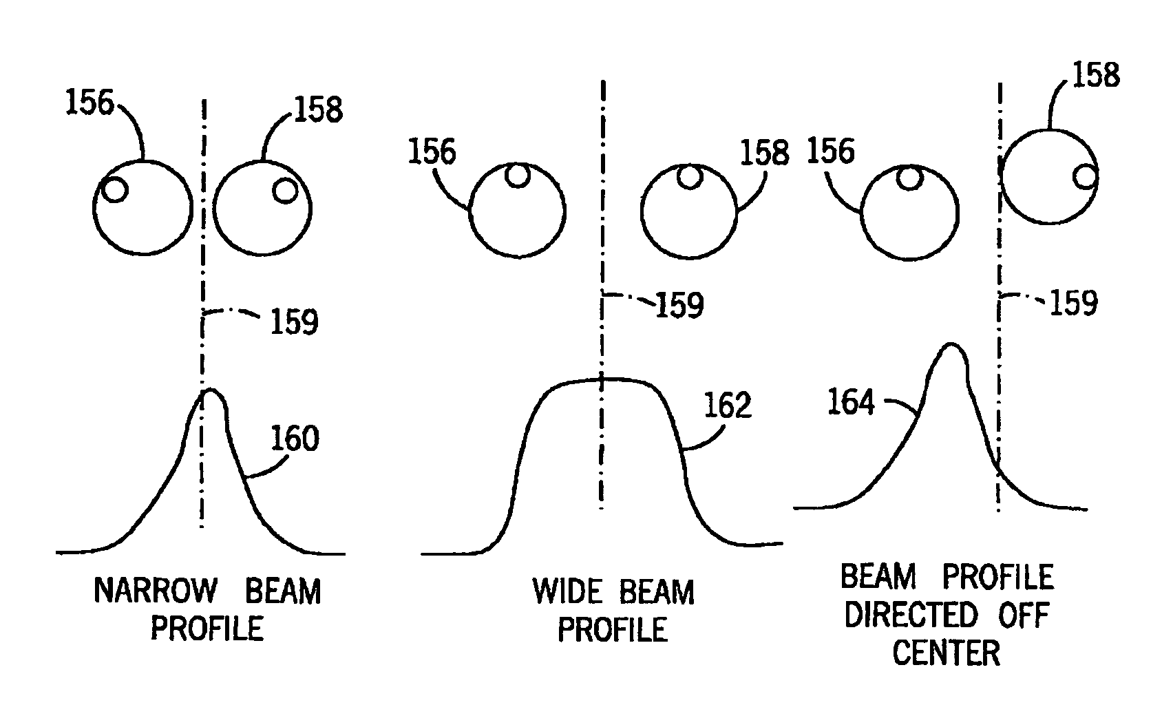
The present invention includes a filtering apparatus for a CT imaging system or equivalently for an x-ray imaging system. The filtering apparatus may be translated along a first axis or a transverse axis to with respect to an attenuation pattern of a subject during an imaging session to reduce radiation exposure to anatomical regions of the subject sensitive to radiation exposure and / or regions from which data is not being acquired.

Description

CROSS REFERENCE TO RELATED APPLICATIONS[0001]The present application is a continuation of U.S. patent application Ser. No. 10 / 064,172 filed Jun. 18, 2002, now U.S. Pat. No. 6,836,535 which is a continuation-in-part of U.S. patent application Ser. No. 10 / 063,420 filed Apr. 22, 2002, both of which are incorporated herein by reference.BACKGROUND OF THE INVENTION[0002]The present invention relates generally to diagnostic imaging and, more particularly, to a method and apparatus of dynamically filtering radiation emitted toward a subject during radiographic imaging.[0003]Typically, in radiographic imaging systems, an x-ray source emits x-rays toward a subject or object, such as a patient or a piece of luggage. Hereinafter, the terms “subject” and “object” may be interchangeably used to describe anything capable of being imaged. The beam, after being attenuated by the subject, impinges upon an array of radiation detectors. The intensity of the attenuated beam radiation received at the det...

Claims


Application Information

Patent Timeline
Patent Type & Authority Patents(United States)
IPC IPC(8): G21K3/00A61B6/03G21K1/10G21K5/02
CPCA61B6/032G21K1/10A61B6/4035A61B6/4488
Inventor TOTH, THOMAS L.BERNSTEIN, TSUR
Owner GENERAL ELECTRIC CO
Learn More