
Device for and method of automatically tracking a moving object

Active Publication Date: 2006-01-31
HANWHA TECHWIN CO LTD +1
View PDF12 Cites 55 Cited by
  • Summary
  • Abstract
  • Description
  • Claims
  • Application Information

AI Technical Summary

Benefits of technology

[0022]Accordingly, it is an object of the present invention to provide an automatic moving object tracking device and a method thereof offering a new concept of tracking which does not require a compensation process for a movement of the camera while utilizing advantages of a disturbance map algorithm, i.e., excellent tracking performance on a moving object with a fixed camera. With an improved processing speed and tracking performance, which is respectively resulted from an acquisition of information about the moving object using a least number of image processes and a proper adaptation to a movement of the moving object and to the changes of a surrounding environment.
[0025]The moving object tracking device includes an input image pre-processing unit improving a processing speed of the input image signal that is input through a photographing process, and then pre-processing the input image signal to eliminate noises from the input image signal.
[0028]The moving object tracking method includes improving a speed of processing the image that is input through the photographing, and then pre-processing the input image to eliminate noises.
[0030]According to the moving object tracking device and method thereof in accordance with the present invention, even a smallest image in size is processed during tracking the moving object. Accordingly, the process speed for the image increases. Further, as the controlling of the photographing direction and the processing of the input image signal are performed separately on the time-division basis during the change of the photographing direction to track the moving object, a compensation for the movement of camera is not required, and thus, burden for a data processing operation is lessened.

Problems solved by technology

Despite some advantages, most of the currently available tracking methods including the above are difficult to commercialize due to problems especially in terms of speed and accuracy.
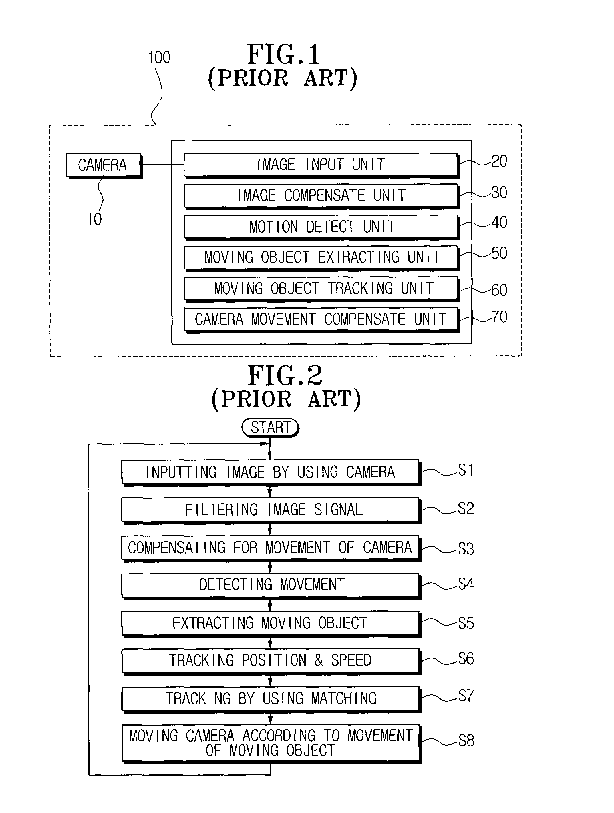
However, when the camera is in motion, image compensation is inevitably required.
For this purpose, the conventional art uses a camera compensation algorithm, which results in an increased amount of data to be processed by the system and consequent overload in data processing.
A block matching algorithm, which has been used for tracking the moving object, also degrades a data processing speed because a size of a block increases as the moving object is moved, and because the size, shape or brightness changes.

Method used


Image

  • Device for and method of automatically tracking a moving object
  • Device for and method of automatically tracking a moving object
  • Device for and method of automatically tracking a moving object

Examples


Embodiment Construction

[0044]Reference will now be made in detail to the present preferred embodiments of the present invention, examples of which are illustrated in the accompanying drawings, wherein like reference numerals refer to the like elements throughout. The embodiments are described in order to explain the present invention by referring to the figures.

[0045]Hereinafter, the preferred embodiments of the present invention will be described in greater detail with reference to the accompanying drawings.

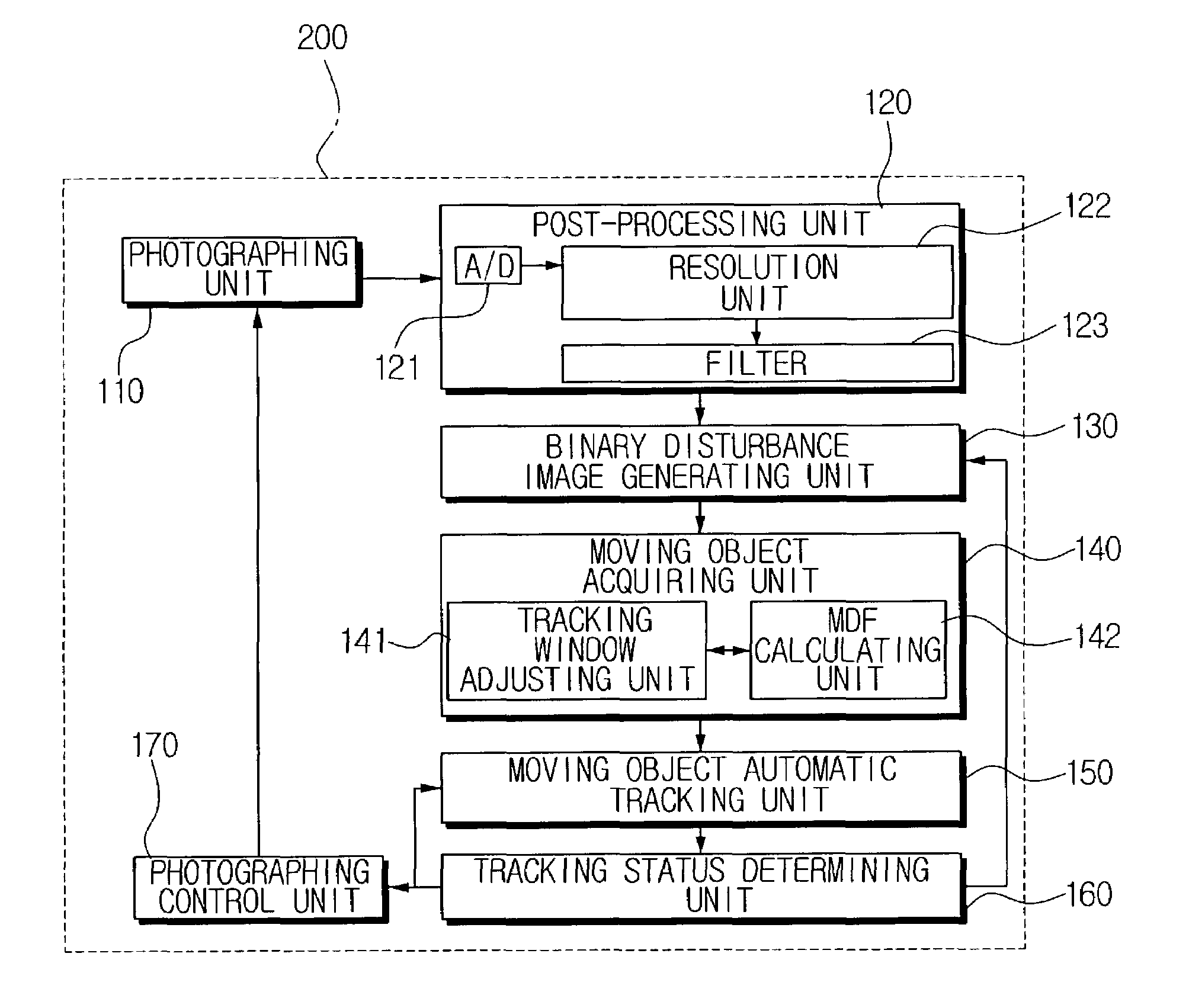
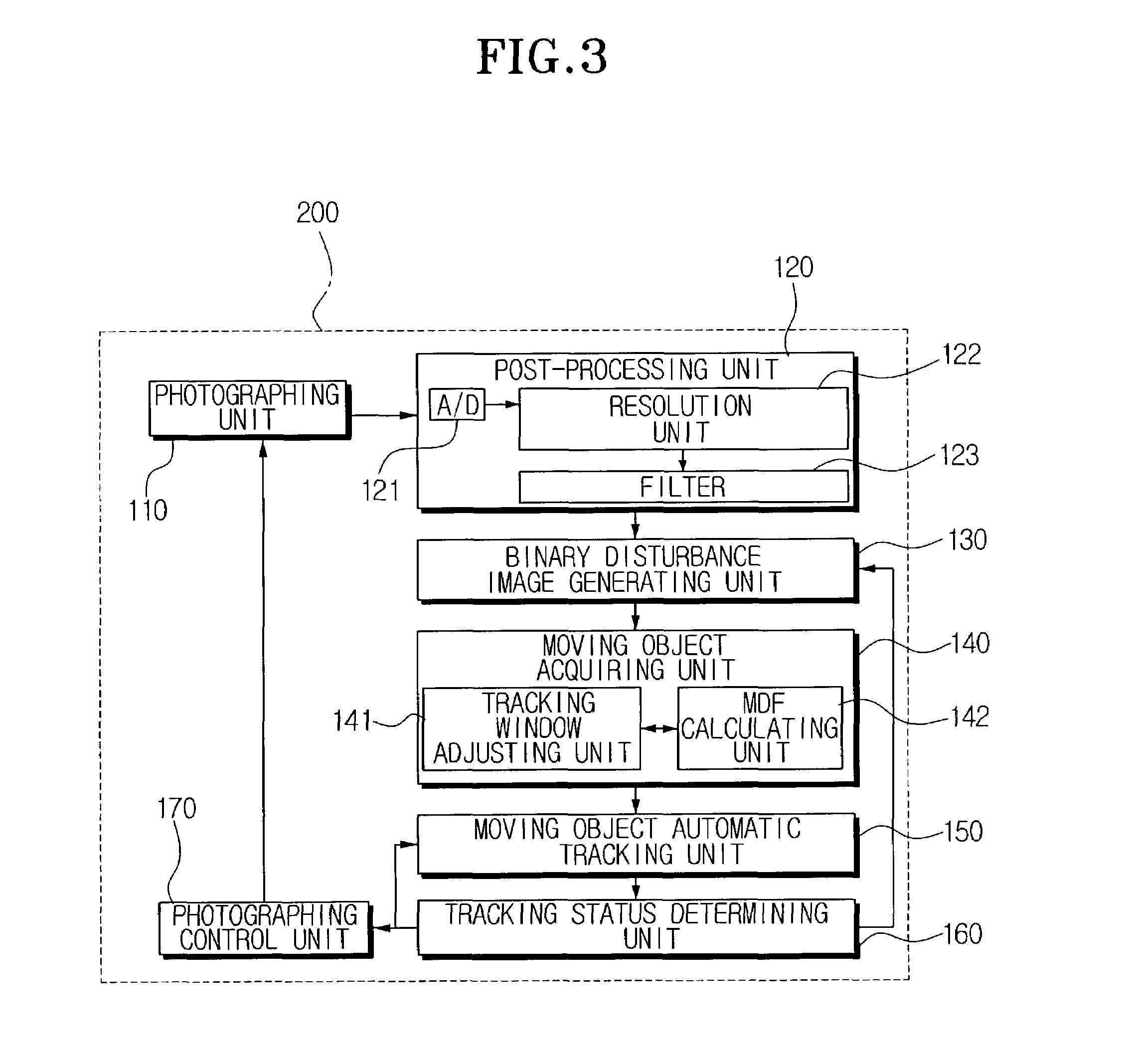
[0046]FIG. 3 is a block diagram of a moving object tracking device 200 according to an embodiment of the present invention.

[0047]The moving object tracking device 200 includes a photographing unit 110, an input image pre-processing (post-processing) unit 120, a binary disturbance image generating unit 130, a moving object acquiring unit 140, a moving object automatic tracking unit 150, a tracking status determining unit 160 and a photographing control unit 170.

[0048]The photographing unit 110 photogra...


PUM


Abstract

An automatic moving object tracking device and a method thereof are capable of tracking a moving object through a signal process of an input image signal of each frame. The moving object tracking device converts a pre-processed input image signal into a binary disturbance image signal, and calculates a motion value of each pixel through an initial tracking window. After locating the tracking window at the pixel where the motion value is a maximum value, a size of the tracking window is adjusted so that the tracking window can include the moving object therein. Next, based on acquired information about the moving object and the tracking window and previously acquired information about previously frames, a pixel in a following frame is estimated to be a next location of the moving object. The tracking window is positioned at the estimated pixel. If the tracking result is satisfied, the tracking of the moving object continues.

Description

CROSS-REFERENCE TO RELATED APPLICATIONS[0001]This application claims the benefit of Korean Patent Application No. 2001-47410, filed Aug. 7, 2001, in the Korean Industrial Property Office, the disclosure of which is incorporated herein by reference.BACKGROUND OF THE INVENTION[0002]1. Field of the Invention[0003]The present invention generally relates to a device for and a method of tracking a moving object, and more particularly, to a device for and a method of automatically detecting a moving object through signal processing on input images and continuously tracking the moving object until the moving object escapes out of a monitoring area.[0004]2. Description of the Related Art[0005]There are various types of tracking systems worldwide for automatically detecting and tracking a moving object based on input image information.[0006]The following are a few representative examples of tracking methods applied in such tracking systems that track the moving object through the input image ...

Claims


Application Information

Patent Timeline
IPC IPC(8): G06K9/00G01B11/00G01S3/786G06T1/00G06T7/20H04N5/232H04N7/18
CPCG06T7/2033G01S3/7865G06T7/246G01B11/00
Inventor CHO, JAE-SOOIIZUKA, HIROSHITANAKA, KAZUHIRO
Owner HANWHA TECHWIN CO LTD
Learn More