Manipulator and its control apparatus and method

a manipulator and control apparatus technology, applied in the field of manipulators, can solve the problems of unsuitable surgery, unfavorable control, and unfavorable control of conventional laparoscope surgery, and achieve the effect of improving controllability and safety

Active Publication Date: 2006-01-31
TERUMO KK
View PDF12 Cites 1049 Cited by
  • Summary
  • Abstract
  • Description
  • Claims
  • Application Information

AI Technical Summary

Benefits of technology

[0013]To overcome the problems involved in the conventional techniques discussed above, it is an object of the present invention to provide a medical manipulator enhanced in controllability and safety, which aligns the orientation of master unit and that of the slave unit without calling the operator's recognition about the process of the alignment when the operator starts controlling the master / slave medical manipulator, but does not effect automatic motions that are out of operator intention and therefore dangerous for medical use, and reflects the operator's intention to the motion of the slave unit even during the alignment operation.

Problems solved by technology

Conventional laparoscope surgery, however, involves some problems.
That is, the operator cannot directly observe the affected part of the patient.
Additionally, there are used forceps only having an opening / closing gripper, not convenient to control and therefore unsuitable for surgery.
This system is complex and large-scaled, and needs high purchasing and maintenance costs.
Moreover, it is not so convenient because of requiring much time to set the system ready for actual operation and being liable to interruption of operation.
Furthermore, since the operator cannot attend closely to the patient during operation and is not available for quick treatment upon emergent accident, the system is insufficient from the viewpoint of safety.
However, these medical manipulators have been developed mainly targeting their functions with affected parts to be operated or treated, and other issues remain unsolved, including how the system is easy to set in the operating room, easy for the operator to use, easy to sterilize and clean, easy to start its actual use, etc. as well as the issue of the cost.
One of problems of conventional techniques is that, if the master / slave medical manipulator is started to move from a status where the control unit (master unit) and the work unit (slave unit) do not coincide in orientation, the slave unit does not move as the user (operator) intends.
This is because, if the operator starts to control the manipulator from those both do not coincide in orientation, the operator cannot accurately recognize the difference between the orientation of the slave unit displayed on the endoscopic monitor and the orientation of the control unit and gets confused.
Under the condition, the manipulator is unreliable in controllability and degrades in safety.
Thus, it involves technical problems to be overcome.
However, this method fails to improve the controllability of the manipulator because the operator must conduct alignment of the orientations every time before starting or re-starting the master / slave motion.
Moreover, since the operator must conduct the alignment for all of plural degrees of freedom of motion, it takes much time for the alignment.
Furthermore, these problems cannot be disregarded also from the standpoint of quick attendance and treatment against unexpected accidents on site.
However, if the alignment of orientations is started under existence of a large difference in orientation, then the distance of automatic movement of the slave unit and its time are large, and the slave unit starts moving in response to the alignment start command.
Therefore, automatic motion out of the operator's intention appears saliently, and the safety issue still remains unsolved.

Method used


Image

  • Manipulator and its control apparatus and method
  • Manipulator and its control apparatus and method
  • Manipulator and its control apparatus and method

Examples


example 1

[0061]Here is explained an application of determining the parameter α in Equation (3). In a medical manipulator having three degrees of freedom of motion including the freedom about the gripper axis in addition to the freedom about the yawing axis and the rolling axis, as shown in FIG. 8, the slave unit of the manipulator have the movable ranges of ±90 degrees about the yawing axis, ±180 degrees about the rolling axis, and 30 degrees of opening angle (of each finger) about the gripper axis (the gripper is shut at 0 degree). The parameter β of the normal master / slave mode is determined as Equation (12). This corresponds to β=1. (Δ⁢⁢θs-yawΔ⁢⁢θS-rollΔ⁢⁢θs-grip)=(100010001)⁢(Δ⁢⁢θm-yawΔ⁢⁢θm-rollΔ⁢⁢θm-grip)(12)

[0062]Since this medical manipulator has a relatively large ovable range about the rolling axis than those about the other two axes, the parameter in the transitional master / slave operative mode was determined as Equation (13) and Equation (14).

[0063]When Δθm and d have the same sig...

example 2

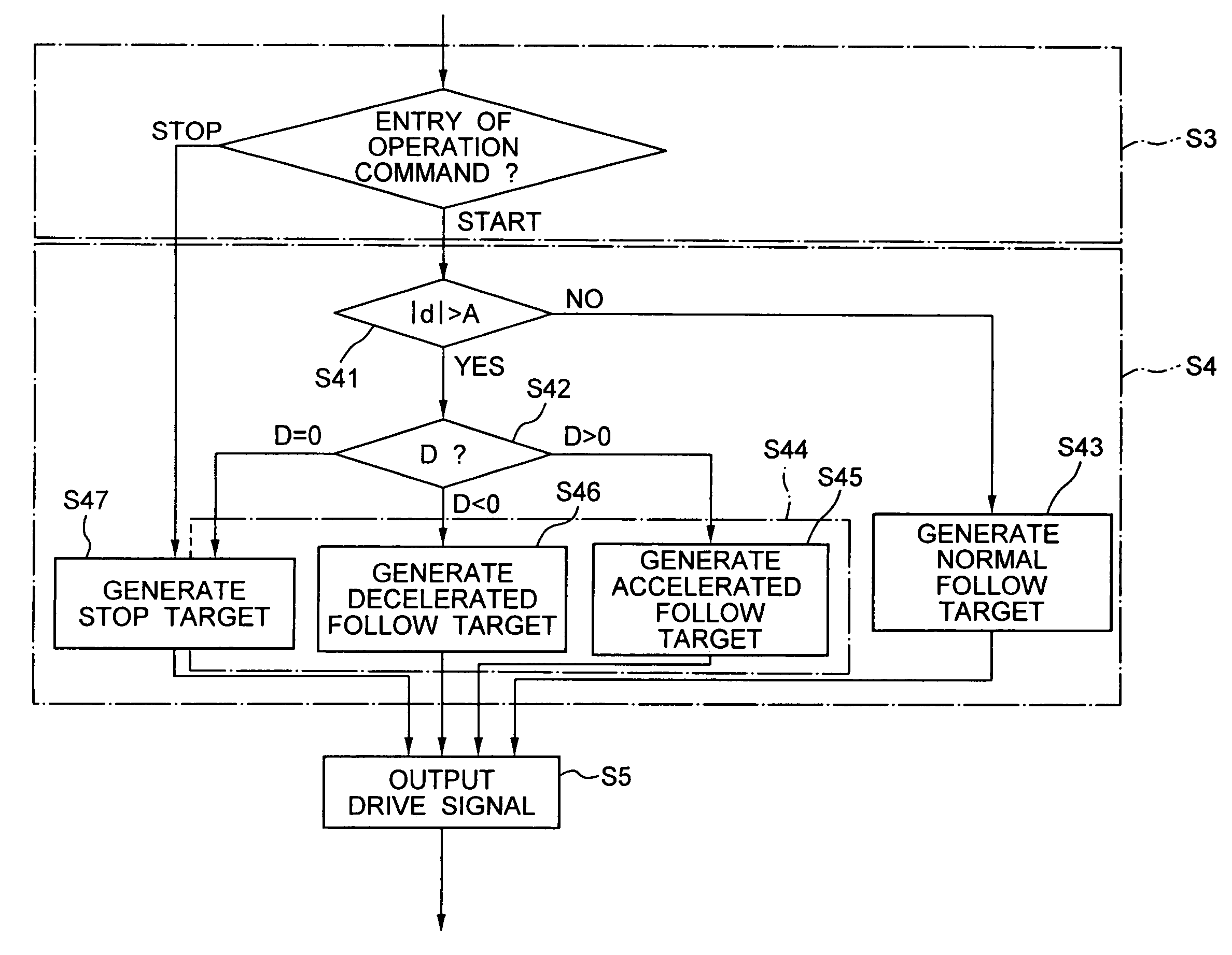
[0066]In case much importance is given to the response to controls also in the transitional master / slave operative mode to realize alignment of orientations in the transitional master / slave operative mode without reducing the speed lower than that of the normal master / slave operative mode, the value of αext under D0), the difference in orientation is removed.

[0067]In contrast, in case much importance is given to safety and an increase of the speed should be prevented, the value of αext under D>0 is set to β because the accelerated follow is desired to cancel in the transitional master / slave operative mode. In this case, the difference in orientation is not removed, but an increase of the speed does not occur. Instead, αext is determined to remove the difference in orientation when D<0.

[0068]If the value of αext under D<0 is always β regardless of the sign of D, this is the case where the slave unit moves relative to the movement of the master unit while the difference d remains unch...

example 3

[0070]Here is explained an application of an embodiment of the invention for resuming the master / slave operation. There is a method of restricting movements about any particular one of the axes of the slave unit in the master / slave operative mode in order to enhance the controllability. The condition restricting a movement about the particular axis corresponds to the condition where the particular axis of the master / slave operative axes is set in a non-master / slave operative mode. The embodiment of the invention is applicable also upon returning to the normal master / slave operative mode. Regarding the release of the restriction as the start command of the master / slave operative mode, transitional master / slave operation may be conducted regarding the axis heretofore restricted.


PUM


Abstract

A manipulator operative in a master/slave operative mode, comprising: a master unit commanding an operation; a slave unit having a work unit; a detector detecting the orientation of the master unit and the orientation of the slave unit; and a control device controlling the slave unit in response to the command from the master unit, wherein the control device includes: a function of determining a non-mater/slave operative mode or a master/slave operative mode; a function of calculating a difference between the orientation of the master unit and the orientationof the slave unit; and a function of comparing the absolute value of the difference with a preset reference value; and depending upon the result of the comparison, determining a normal master/slave operative mode or a transitional master/slave operative mode, in the master/slave operative mode, the transitional master/slave operative mode is a transitional mode from the non-master/slave operative mode to the master/slave operative mode.

Description

CROSS-REFERENCE TO RELATED APPLICATIONS[0001]This application is based upon and claims the benefit of priority from prior Japanese Patent Application No. 2003-096819, filed on Mar. 31, 2003, the entire contents of which are incorporated herein by reference.BACKGROUND OF THE INVENTION[0002]1. Field of the Invention[0003]The present invention relates generally to a manipulator, and its control device and method. More specifically, the invention relates to a medical manipulator operative in a master / slave mode, and its control device and method.[0004]2. Related Background Art[0005]In conventional laparoscope surgery such as laparoscopic cholecystectomy, an endoscope and forceps are inserted into an abdominal cavity through trocars set in small incisions made in the abdomen of a patient. Then, an operator conducts operation while watching the image acquired by the endoscope on a monitor. Since this type of operation does not need to open the abdomen, physical burden on the patient is al...

Claims


Application Information

Patent Timeline
Patent Type & Authority Patents(United States)
IPC IPC(8): G05B15/00G05B19/00B25J3/00A61B17/00A61B17/28A61B19/00
CPCA61B19/22G06F19/3406A61B2019/2223A61B19/2203A61B34/30A61B34/37A61B34/70G16H40/63H04B1/40H04W4/10
Inventor SUNAOSHI, TAKAMITSU
Owner TERUMO KK
Why Eureka
Try Eureka