Method for determining and tracking the position and orientation of a magnetic field sensor

Inactive Publication Date: 2006-01-31
RHEINMETALL DEFENCE ELECTRONICS
View PDF2 Cites 12 Cited by
  • Summary
  • Abstract
  • Description
  • Claims
  • Application Information

AI Technical Summary

Benefits of technology

[0006]The advantage of the method according to embodiments of the invention is that the area directly surrounding the magnetic field sensor in the real magnetic field space is used for correcting the measuring values. Thus, the method still delivers good results, even with considerable differences locally in the interference of the mag

Problems solved by technology

Thus, the method still delivers good results, even with considerable differences locally in the i

Method used


Image

  • Method for determining and tracking the position and orientation of a magnetic field sensor
  • Method for determining and tracking the position and orientation of a magnetic field sensor
  • Method for determining and tracking the position and orientation of a magnetic field sensor

Examples


Example

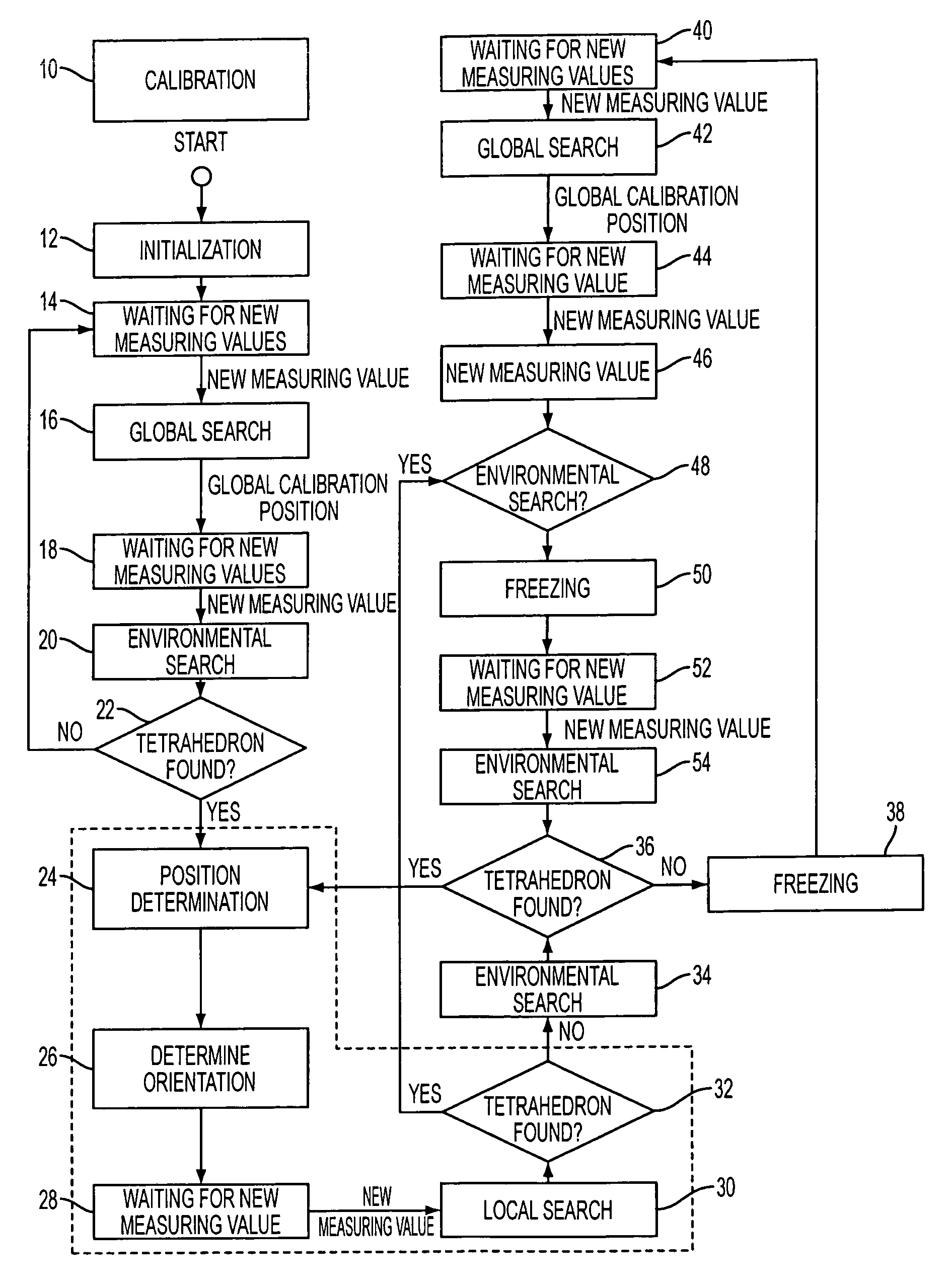
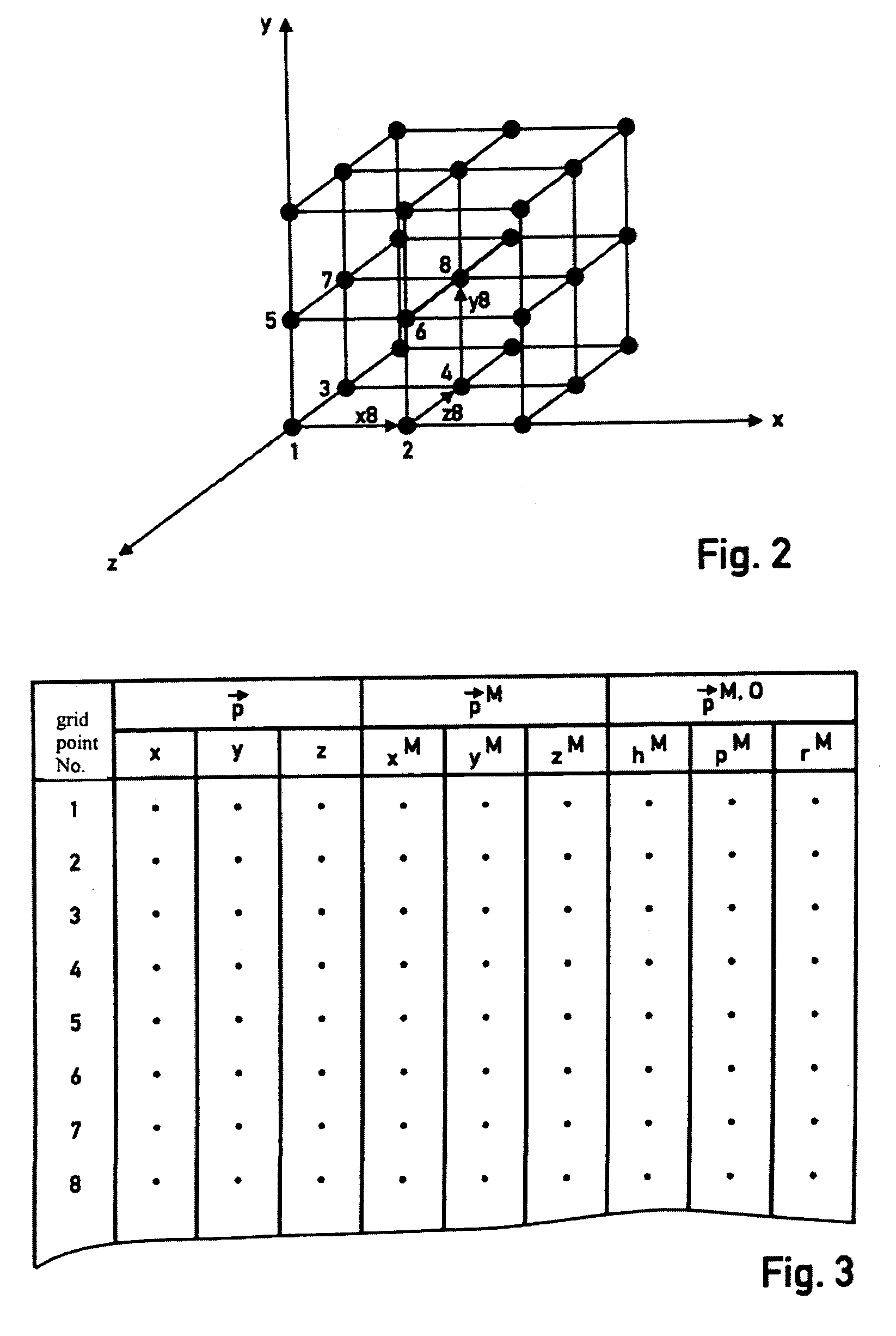
[0022]The method illustrated in the flow chart shown in FIG. 1 is used to correctly determine a position and orientation of a magnetic field sensor that moves within a three-dimensional magnetic field space, even if the magnetic field generated in the magnetic field space is disturbed or distorted in some regions and the magnetic field sensor delivers incorrect measuring values for the true position and true orientation in those regions. In the following, the measuring values output by the magnetic field sensor are referred to as measuring position and measuring orientation. The method is preceded by a calibration mode in which the magnetic field space is structured into a three-dimensional grid with equidistant grid points. One grid point is preferably located at the point of origin of a three-dimensional coordinate system x, y, z that in the following is called the real space coordinate system. Each grid point thus has a position vector {right arrow over (p)} with the coordinates ...


PUM


Abstract

With a method for determining and tracking a changing, true position and orientation of a magnetic field sensor within a three-dimensional magnetic field space from the values measured by the magnetic field sensor, the magnetic field space is structured in a preceding calibration mode into a three-dimensional grid with equidistant grid points. All values measured by the magnetic field sensor are then stored in a calibration table as calibration positions and calibration orientations allocated to the real positions of the grid points in the magnetic field space. A linear interpolating transformation of the measuring position in the real magnetic field space is executed for the measuring values from the magnetic field sensor by using respectively four calibration positions taken from the calibration table, which span a tetrahedron that encloses the measuring position.

Description

FIELD OF THE INVENTION[0001]The invention relates to a method for determining and tracking the changing, true position and orientation of a magnetic field sensor within a three-dimensional magnetic field space with the aid of the values supplied by the magnetic field sensor as measuring position and measuring orientation.BACKGROUND OF THE INVENTION[0002]For a realistic simulation of images that change when the head position and head orientation of the observer changes, e.g. of panoramic image details shown on the night-vision goggles of a pilot, the observer's point of sight and thus his / her exact head position and orientation must be known for a precise calculation of the image detail that changes with the head movement. A magnetic field is generated in a real space in which the observer is seated, e.g. in the cockpit of an airplane or a helicopter, and a magnetic field sensor is attached to the head of the observer for sensing the magnetic field. The values measured by the magneti...

Claims


Application Information

Patent Timeline
IPC IPC(8): G01C17/38G01B7/004G06F3/00G06F3/01
CPCG06F3/012G01B7/004
Inventor HARLE, NORBERT
Owner RHEINMETALL DEFENCE ELECTRONICS
Why Eureka
Try Eureka