Method and apparatus for detecting ionization signal in diesel and dual mode engines with plasma discharge system

a plasma discharge and ionization signal technology, applied in the direction of machines/engines, electrical control, instruments, etc., can solve the problems of large differences in the advantages and disadvantages of diesel and spark-ignited engines, the typical diesel engine cannot achieve the very low nosub>x/sub>and particulate emissions, and the particulate emissions are not high enough

Active Publication Date: 2006-02-07
WOODWARD GOVERNOR CO
View PDF18 Cites 97 Cited by
  • Summary
  • Abstract
  • Description
  • Claims
  • Application Information

AI Technical Summary

Problems solved by technology

These emission reductions represent a continuing challenge to engine design due to the NOx-diesel particulate emission and fuel economy tradeoffs associated with most emission reduction strategies.
As a result, there are important differences in the advantages and disadvantages of diesel and spark-ignited engines.
Typical diesel engines, however, cannot achieve the very low NOx and particulate emissions levels that are possible with premixed charge spark ignited engines.
Due to the mixing controlled nature of diesel combustion a large fraction of the fuel exists at a very fuel rich equivalence ratio, which is known to lead to particulate emissions.
Spark ignited engines, on the other hand, have nearly homogeneous air fuel mixtures that tend to be either lean or close to stoichiometric, resulting in very low particulate emissions.
The high temperatures, in turn, cause high NOx emissions.
Lean burn spark ignited engines, on the other hand, burn their fuel at much leaner equivalence ratios which results in significantly lower temperatures leading to much lower NOx emissions.
Stoichiometric spark ignited engines, on the other hand, have high NOx emissions due to the high flame temperatures resulting from stoichiometric combustion.
Carbon adheres to the circumference of the ceramic heating portion of the glow plug and reduces the insulation resistance between the exposed electrode used for ion current detection and the grounded portion (plug housing and cylinder head) that is insulated from the electrode.
When this happens, the ion current detected shows a waveform different from a desired one due to occurrence of the leakage current, and such an incorrect detection result causes deterioration in the accuracy of ignition stage and flame failure detections.
Furthermore, the electrode is almost completely exposed into the combustion chamber and the space between the housing and the electrode is narrow.
For this reason, there is a danger that the electrode is shorted to the ground and the housing is made conductive due to adhesion of carbon to the electrode surface, resulting in an error in detecting ion current.
Additionally, since the ion current detecting electrode supported at the tip of the glow plug directly touches a flame having a high temperature, stresses tend to be concentrated in the neighborhood of the ion current detecting electrode and could damage the ceramic glow plug such as to crack it.

Method used


Image

  • Method and apparatus for detecting ionization signal in diesel and dual mode engines with plasma discharge system
  • Method and apparatus for detecting ionization signal in diesel and dual mode engines with plasma discharge system
  • Method and apparatus for detecting ionization signal in diesel and dual mode engines with plasma discharge system

Examples


Embodiment Construction

[0028]The present invention provides an apparatus and method to detect combustion ion current in a diesel combustion engine for use in various control functions that use ionization signals such as EGR (Exhaust Gas Recirculation) control, diesel injection timing control from ignition, and cold starts of diesel engines. As used herein, the term “diesel engine” refers to typical diesel engines, HCCI engines and dual mode engines.

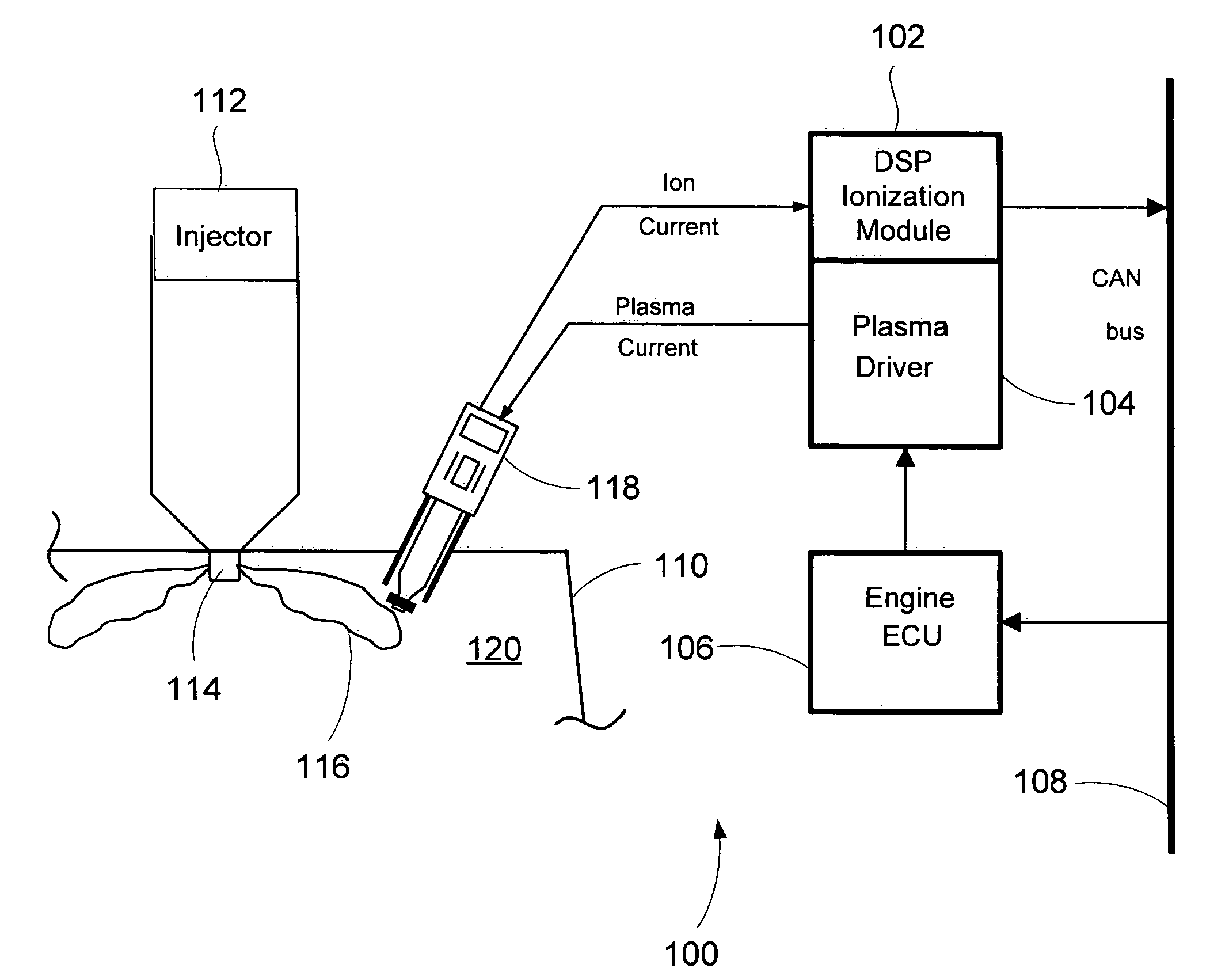
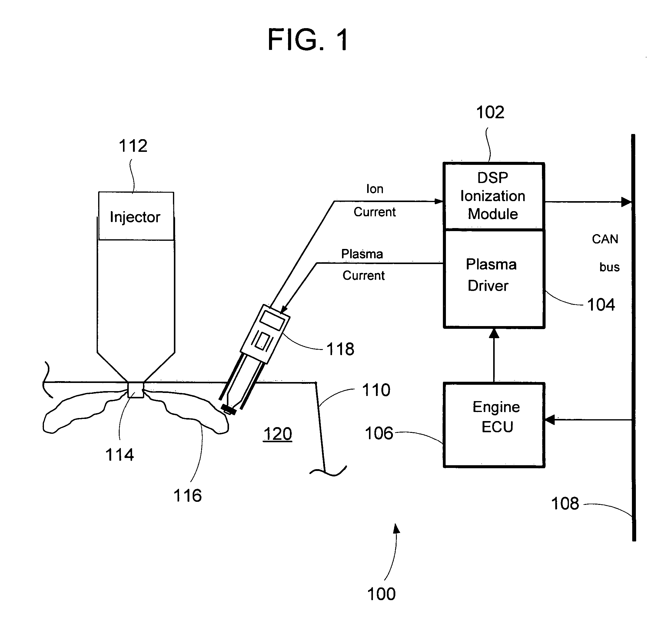
[0029]Referring initially to FIG. 1, a system 100 exemplifying the present invention is shown. The system includes an ionization module 102, a plasma driver 104, an engine electronic control unit (ECU) 106, and a diesel engine. The ionization module 102 communicates with the ECU 106 and other modules via, for example, the CAN (Controller Area Network) bus 108. While the ionization module 102, the plasma driver 104 and the engine control unit 106 are shown separately, it is recognized that the components 102, 104, 106 may be combined into a single module or be p...


PUM

PropertyMeasurementUnit
ion currentaaaaaaaaaa
threshold valueaaaaaaaaaa
combustionaaaaaaaaaa

Abstract

An apparatus and method to detect combustion conditions using ion signals for use in a feedback control of a diesel engine is presented. The apparatus is a spark plug type of sensor or a sensor integrated with a fuel injector. The spark plug type of sensor is used to provide a cold start mechanism combined with an ion sensing device.

Description

CROSS-REFERENCE TO RELATED PATENT APPLICATIONS[0001]This patent application claims the benefit of U.S. Provisional Patent Application No. 60 / 516,148, filed Oct. 31, 2003.FIELD OF THE INVENTION[0002]The present invention relates generally to ignition systems in diesel engines, and more particularly relates to such systems in diesel engines in which combustion is started with a plasma discharge system.BACKGROUND OF THE INVENTION[0003]Government agencies and industry standard setting groups are reducing the amount of allowed emissions in stoichiometric and diesel engines in an effort to reduce pollutants in the environment. For example, over the past decade, increasingly more stringent heavy duty on-highway engine emission regulations have led to the development of engines in which NOx and diesel particulate emissions have been reduced by as much as seventy percent and ninety percent, respectively. Proposed regulations for new heavy duty engines require additional NOx and diesel partic...

Claims


Application Information

Patent Timeline
Patent Type & Authority Patents(United States)
IPC IPC(8): F02P15/00G01L23/22F02B1/12F02D35/02F02D37/02F02D41/14F02D41/30F02D41/38F02P9/00
CPCF02P9/007F02B1/12F02D41/3035F02P2017/125F02P15/006F02D35/021F02M57/005
Inventor TOZZI, LUIGI P.BENSON, KELLY J.VIELE, MATTHEW
Owner WOODWARD GOVERNOR CO
Why Eureka
Try Eureka