Vapor escape microchannel heat exchanger

Inactive Publication Date: 2006-02-07
VERTIV CORP
View PDF207 Cites 200 Cited by
  • Summary
  • Abstract
  • Description
  • Claims
  • Application Information

AI Technical Summary

Benefits of technology

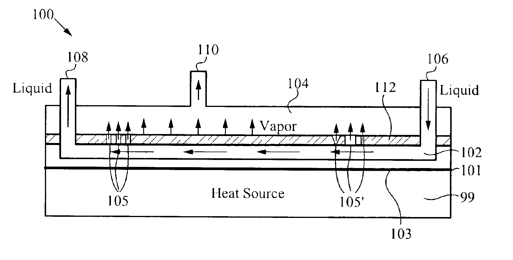
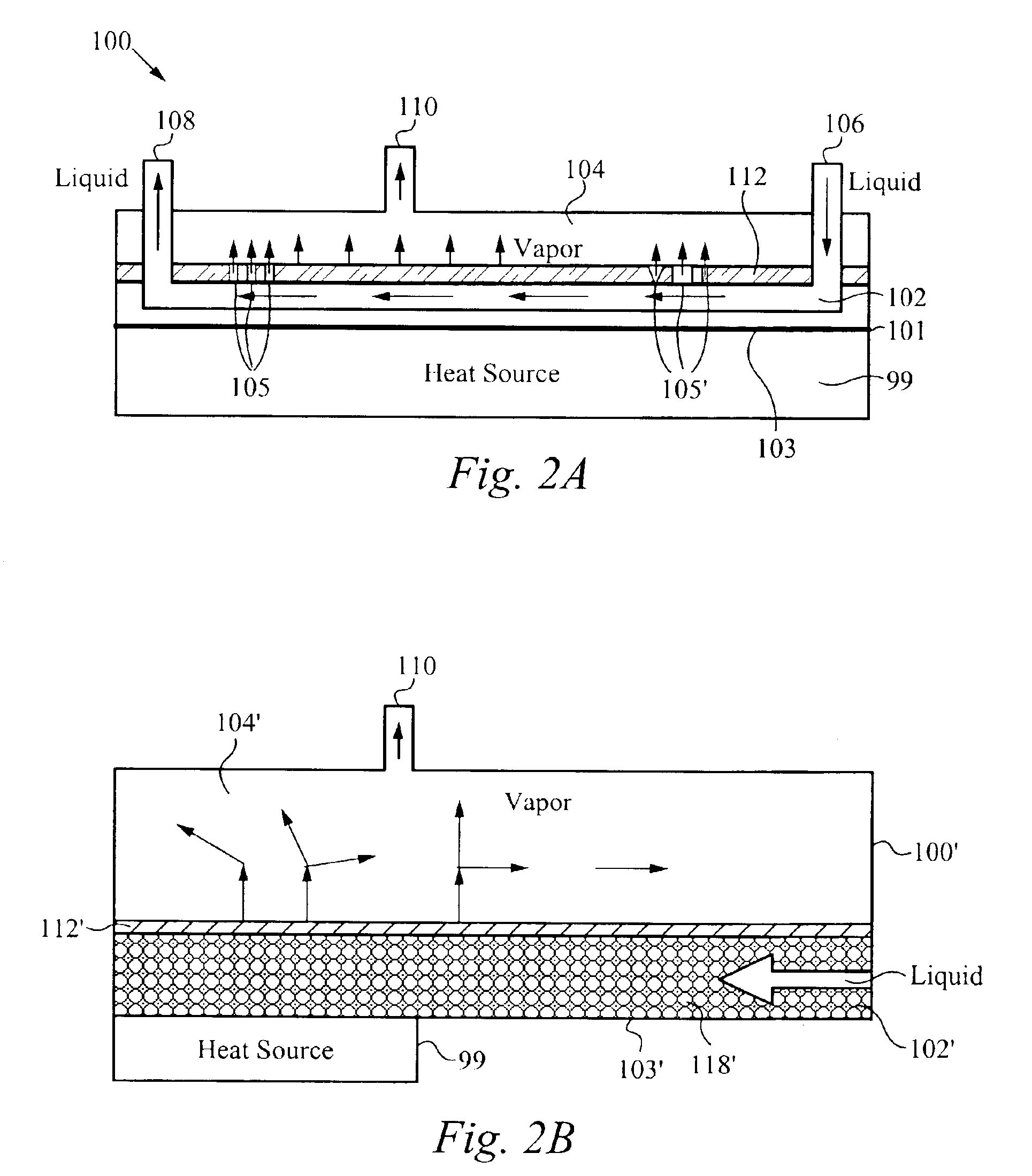
[0012]In yet another aspect of the invention, a vapor escape membrane for use in a heat exchanging device, whereby the heat exchanging device runs liquid into a cooling region that is positioned adjacent to the heat producing device. The vapor escape membrane comprises a porous surface which removes vapor produced from the liquid in the cooling region. The membrane is configured to confine the liquid only within the cooling region. The vapor escape membrane transfers vapor to a vapor region within the heat exchanging device, whereby the membrane is configured to prevent liquid in the cooling region from entering the vapor region. The vapor escape membra

Problems solved by technology

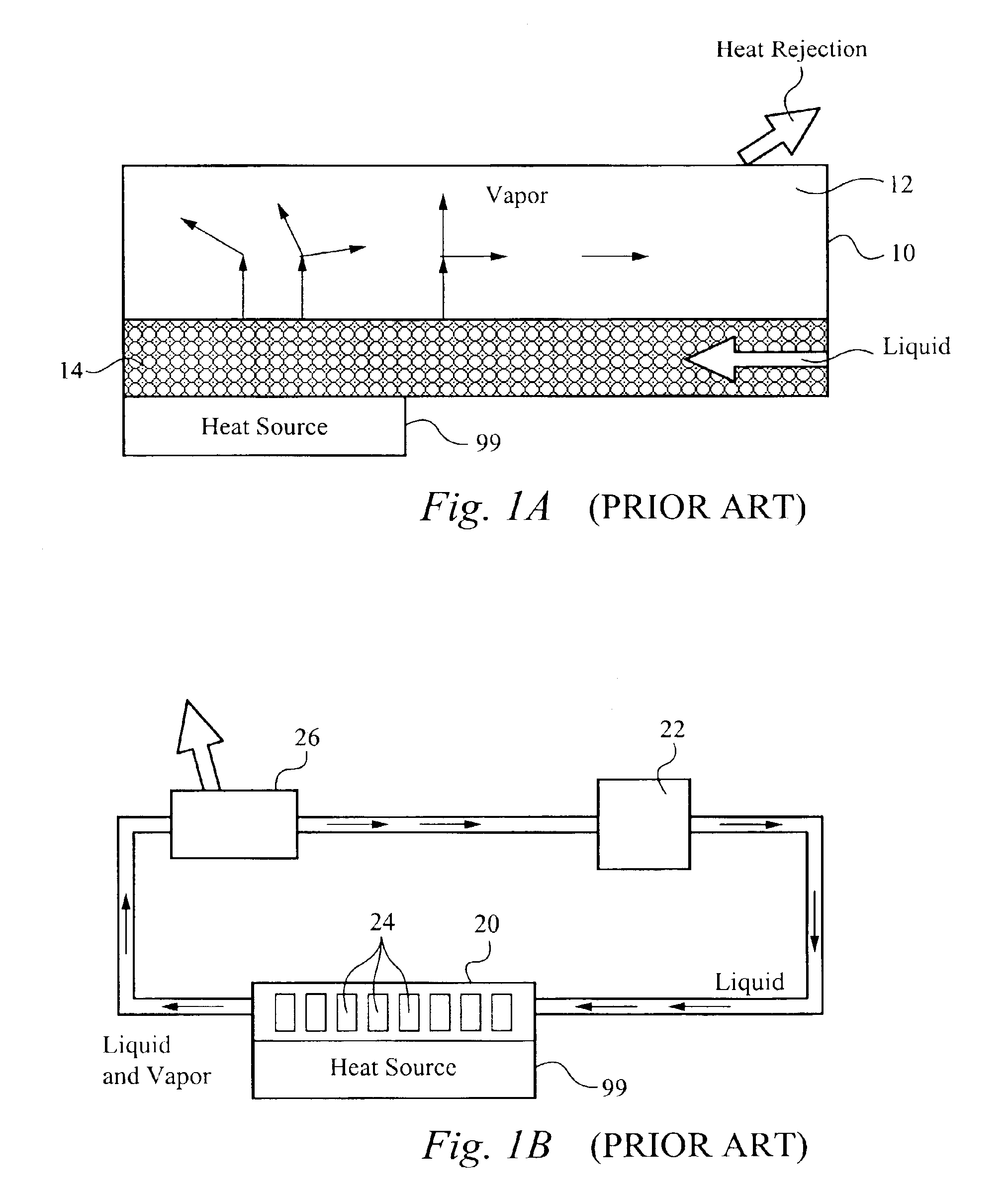
However, a problem with the geometry of the heat pipe 10 is that the flowrate of the liquid is limited by the capillary pressure available for drawing liquid back into the wick 14.
However, thickening the wick structure 14 increases the heat transfer resistance for conduction normal to the wick structure 14 itself, thereby renderi

Method used


Image

  • Vapor escape microchannel heat exchanger
  • Vapor escape microchannel heat exchanger
  • Vapor escape microchannel heat exchanger

Examples


Embodiment Construction

[0026]Reference will now be made in detail to the preferred and alternative embodiments of the invention, examples of which are illustrated in the accompanying drawings. While the invention will be described in conjunction with the preferred embodiments, it will be understood that they are not intended to limit the invention to these embodiments. On the contrary, the invention is intended to cover alternatives, modifications and equivalents, which may be included within the spirit and scope of the invention as defined by the appended claims. Furthermore, in the following detailed description of the present invention, numerous specific details are set forth in order to provide a thorough understanding of the present invention. However, it should be noted that the present invention may be practiced without these specific details. In other instances, well known methods, procedures and components have not been described in detail as not to unnecessarily obscure aspects of the present in...


PUM


Abstract

A vapor escape membrane for use in a heat exchanging device, including a heat pipe or heat sink that runs liquid into a cooling region positioned adjacent to the heat producing device, the vapor escape membrane comprising: a porous surface for removing vapor produced from the liquid in the cooling region, the membrane configured to confine the liquid only within the cooling region. The vapor escape membrane transfers vapor to a vapor region within the heat exchanging device, wherein the membrane is configured to prevent liquid in the cooling region from entering the vapor region. The membrane is configured to include a hydrophobic surface between the membrane and the cooling region, wherein the liquid in the cooling region does not flow through the porous surface. The vapor escape membrane includes a plurality of apertures for allowing vapor to transfer therethrough, each of the apertures having a predetermined dimension.

Description

RELATED APPLICATIONS[0001]This Patent Application claims priority under 35 U.S.C. 119 (e) of the co-pending U.S. Provisional Patent Application, Ser. No. 60 / 420,557 filed Oct. 22, 2002, and entitled “VAPOR ESCAPE MICROCHANNEL HEAT EXCHANGER WITH SELF ATTACHMENT MEANS”. The Provisional Patent Application, Ser. No. 60 / 420,557 filed Oct. 22, 2002, and entitled “VAPOR ESCAPE MICROCHANNEL HEAT EXCHANGER WITH SELF ATTACHMENT MEANS” is also hereby incorporated by reference.FIELD OF THE INVENTION[0002]The present invention relates to cooling of a heat producing device using a heat exchanger, in general, and in particular, a vapor escape membrane coupled to a heat exchanger and a method of providing the same.BACKGROUND OF THE INVENTION[0003]A variety of devices and applications are present which require cooling of devices that have very high heat fluxes, such as in the range of 100-1000 W / cm2. These devices include integrated electronic circuits in microprocessors, laser diodes, and power se...

Claims


Application Information

Patent Timeline
IPC IPC(8): F28F7/00H01L23/427
CPCH01L23/427H01L23/4275H01L2924/0002H01L2924/00
Inventor ZHOU, PENGGOODSON, KENNETHSUNTIAGO, JUAN
Owner VERTIV CORP
Why Eureka
Try Eureka