LED lamp cooling apparatus with pulsating heat pipe

a technology of led lamps and heat pipes, which is applied in the direction of lighting and heating apparatus, indirect heat exchangers, semiconductor devices of light sources, etc., can solve the problems of limited heat dissipation efficiency of led lamps, inconvenient for high-power consumption led lamps, and reduced work efficiency and service li

Inactive Publication Date: 2008-05-22
HON HAI PRECISION IND CO LTD
View PDF8 Cites 106 Cited by
  • Summary
  • Abstract
  • Description
  • Claims
  • Application Information

AI Technical Summary

Problems solved by technology

If this heat is not quickly removed, these LEDs may overheat, and thus their work efficiency and service life can be significantly reduced.
However, this method is only suitable for low power consumption LED lamps, and is not suitable for high power consumption LED lamps.
The heat dissipation efficiency of these heat pipes, however, is limited by their low heat flux per unit area, and consequently these heat pipes are easy to dry out when subjected to a large amount of heat.

Method used


Image

  • LED lamp cooling apparatus with pulsating heat pipe
  • LED lamp cooling apparatus with pulsating heat pipe
  • LED lamp cooling apparatus with pulsating heat pipe

Examples


first embodiment

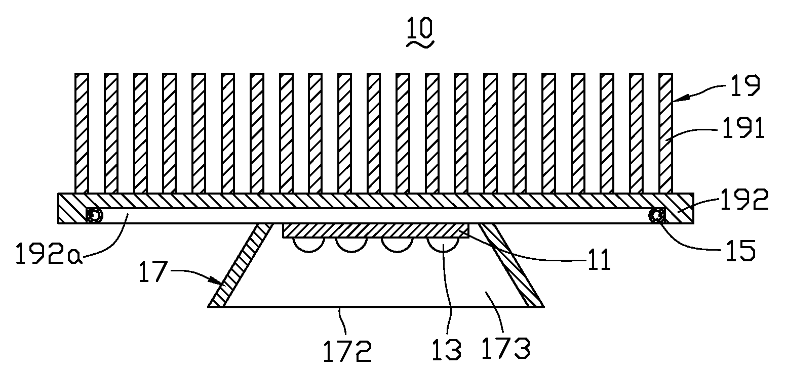
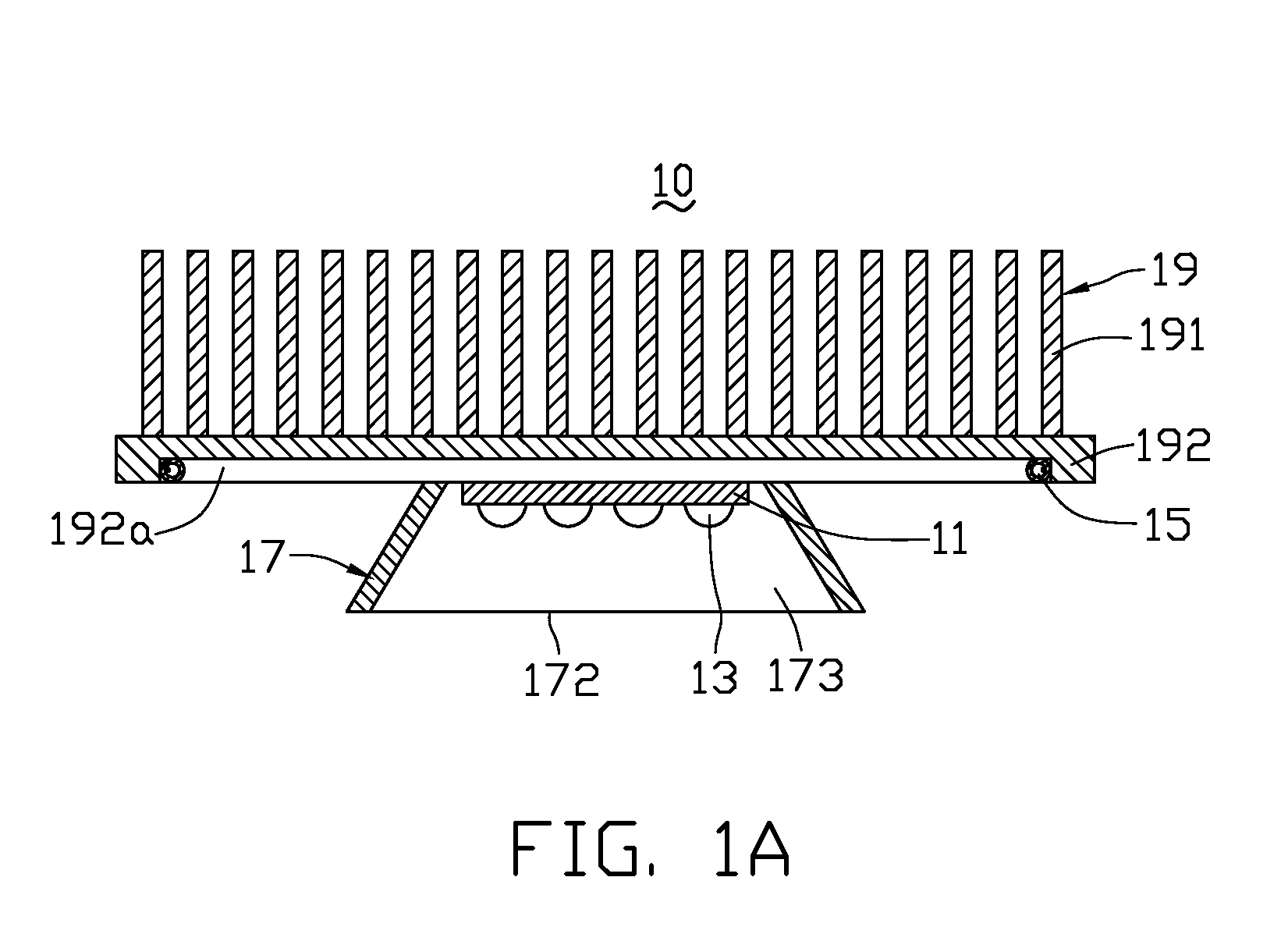
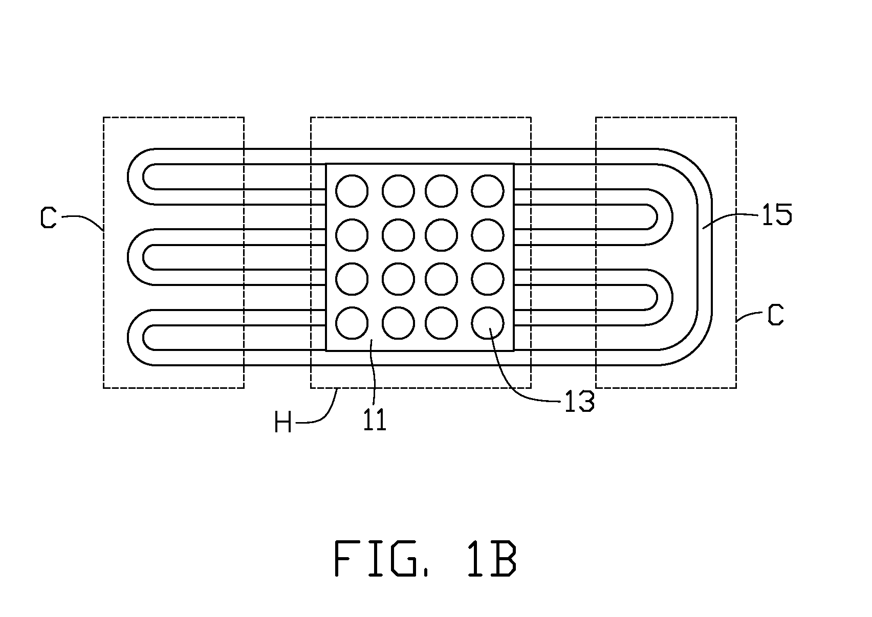
[0028]FIGS. 1A-1B illustrate an LED lamp cooling apparatus 10 in accordance with the present invention. The cooling apparatus 10 includes a substrate 11, a plurality of LEDs 13 electrically connected with the substrate 11, a pulsating heat pipe 15 thermally connected with the substrate 11, a reflector 17 enclosing the LEDs 13 and the substrate 11, and a heat sink 19 attached to the pulsating heat pipe 15 for dissipating heat generated by the LEDs 13 to ambient atmosphere. Shape and structure of the heat sink 19 can be diverse. In this embodiment, the heat sink 19 includes a planar base 192 and a plurality of cooling fins 191 extending upwardly from the base 192.

[0029]The substrate 11 of the cooling apparatus 10 is a circuit board preferably made of a highly thermally conductive material. The substrate 11 may be a metal-based circuit board, such as a metal core printed circuit board (MCPCB), to improve thermal conductivity. Alternatively, the substrate may be a ceramic circuit board....

fifth embodiment

[0040]FIGS. 7A-7B illustrate an LED cooling apparatus 70 in accordance with the present invention. The cooling apparatus 70 includes a substrate 71, a plurality of LEDs 73 electrically connected with the substrate 71, a reflector 77 enclosing the substrate 71 and the LEDs 73, a heat sink 79 and a pulsating heat pipe 75 thermally connected with both the substrate 71 and the heat sink 79.

[0041]The reflector 77 has a cup-like shape and is made of a material of high thermal conductivity such as copper or aluminum. The reflector 77 has a bottom chassis 772 on which the substrate 71 and the LEDs 73 are disposed, and defines an opening 771 at a top end thereof acting as a light exit. An inner surface of the reflector 77 has a light-reflecting material applied thereon, so that light emitted from the LEDs 73 can be reflected and guided towards the opening 771. The heat sink 79 has a U-shaped base 792 defining a recess 793 for the reflector 77 to be accommodated therein, and a plurality of co...

seventh embodiment

[0044]FIGS. 9A-9B illustrate an LED lamp cooling apparatus 90 in accordance with the present invention. In this embodiment, the pulsating heat pipe 95 is formed as a closed loop and is configured to have a shape conforming to the U-shaped profile of the reflector 97. Alternatively, the pulsating heat pipe 95 can also be an open loop as shown in FIG. 9C. The pulsating heat pipe 95 has a plurality of U-shaped heat receiving portions 954 in a central area thereof and a plurality of U-shaped heat radiating portions 955 at a circumference thereof. The reflector 97 is made of a highly thermally conductive material such as copper, aluminum or alloys thereof, and the pulsating heat pipe 95 is tightly and thermally attached to or embedded in an inner surface of the reflector 97. The heat receiving portions 954 and heat radiating portions 955 are evenly distributed across the inner surface of the reflector 97. The LEDs 93 are disposed on and electrically connects with the substrate 91. The su...


PUM


Abstract

An LED lamp cooling apparatus (10) includes a substrate (11), a plurality of LEDs (13) electrically connected with the substrate, a heat sink (19) for dissipation of heat generated by the LEDs and a pulsating heat pipe (15) thermally connected with the heat sink. The pulsating heat pipe includes a plurality of heat receiving portions (154) and a plurality of heat radiating portions (155), and contains a working fluid (153) therein. The substrate is attached to the heat receiving portions of the pulsating heat pipe and the heat sink is attached to the heat radiating portions of the pulsating heat pipe. The heat generated by the LEDs is transferred from the heat receiving portions to the heat radiating portions of the pulsating heat pipe through pulsation or oscillation of the working fluid in the pulsating heat pipe.

Description

BACKGROUND OF THE INVENTION[0001]1. Field of the Invention[0002]The present invention relates generally to cooling apparatus for use with light emitting diodes (LEDs), and more particularly to an LED lamp cooling apparatus using a pulsating heat pipe for improving heat dissipation.[0003]2. Description of Related Art[0004]With the continuing development of scientific technology and the raise of people's consciousness of energy saving, LEDs have been widely used in the field of illumination due to their small volume in size and high efficiency. It is well known that LEDs generate heat when they emit light. If this heat is not quickly removed, these LEDs may overheat, and thus their work efficiency and service life can be significantly reduced. This is particularly true when LEDs are used in an LED lamp in which the LEDs are arranged side-by-side in large density.[0005]A traditional method of solving the heat dissipation problem is using a plurality of cooling fins attached to a base o...

Claims


Application Information

Patent Timeline
Patent Type & Authority Applications(United States)
IPC IPC(8): F28F1/10
CPCF21K9/00F21V29/004F21V29/006F21Y2101/02F21V29/763F21V7/22Y10S362/80F21V29/505F28D15/0266F21V29/51F21V29/773F28D15/0275F21Y2105/10F21Y2115/10F21V29/717F21V7/24F21V29/74
Inventor CHANG, CHANG-SHENLIU, JUEI-KHAIWANG, CHAO-HAOPEI, HSIEN-SHENG
Owner HON HAI PRECISION IND CO LTD
Why Eureka
Try Eureka