Heat dissipation devices for and LED lamp set

a technology of heat dissipation device and led lamp, which is applied in the field of heat dissipation of lightemitting diode (led) lamps, can solve problems such as noise problems, performance degradation or even damage, and the risk of damage to led lamps

Inactive Publication Date: 2007-04-19
NATIONAL TSING HUA UNIVERSITY
View PDF23 Cites 105 Cited by
  • Summary
  • Abstract
  • Description
  • Claims
  • Application Information

AI Technical Summary

Benefits of technology

[0007] This invention discloses heat dissipation devices for LED lamps with a plate-type heat spreader as the core unit. The plate-type heat spreader is either a flat-plate heat pipe or a metal plate embedded with heat pipes. The high-power LED lamps are thermally connected to the bottom surface of the heat spreader so that the heat generated by the LED lamps is absorbed by the evaporation region of the flat-plate heat pipe or the embedded heat pipes. The heat is spread by internal vapor motion...

Problems solved by technology

The high power LED light devices produce considerable amount of heat, which may cause performance degrade or even damage if the heat is not removed from the LED chips efficiently.
Traditional adoption of fans for active cooling system not only introduces noise problems but also brings risk of damage to a LED lamp if the fan is out of order.
However, ...

Method used


Image

  • Heat dissipation devices for and LED lamp set
  • Heat dissipation devices for and LED lamp set
  • Heat dissipation devices for and LED lamp set

Examples


Embodiment Construction

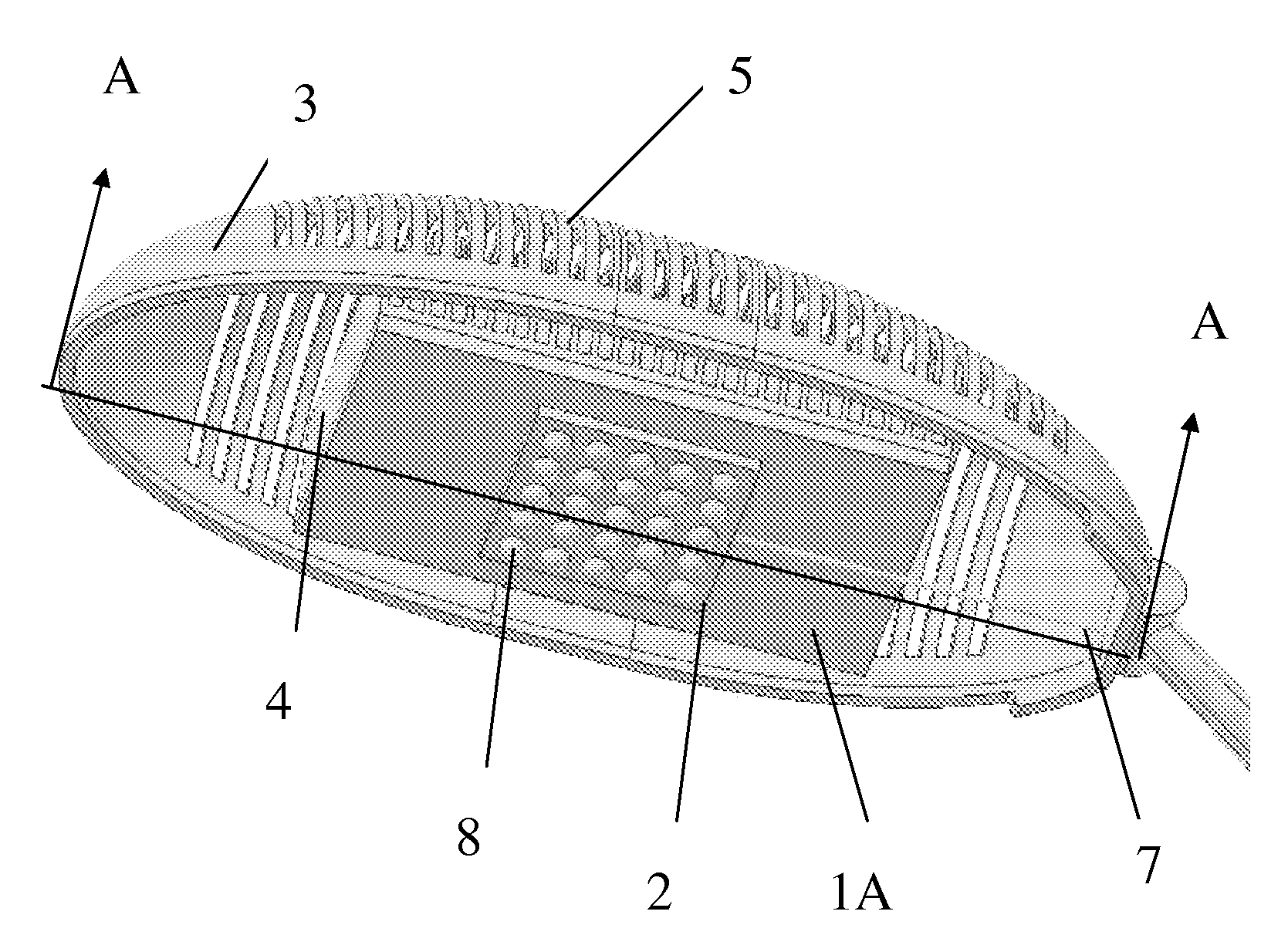
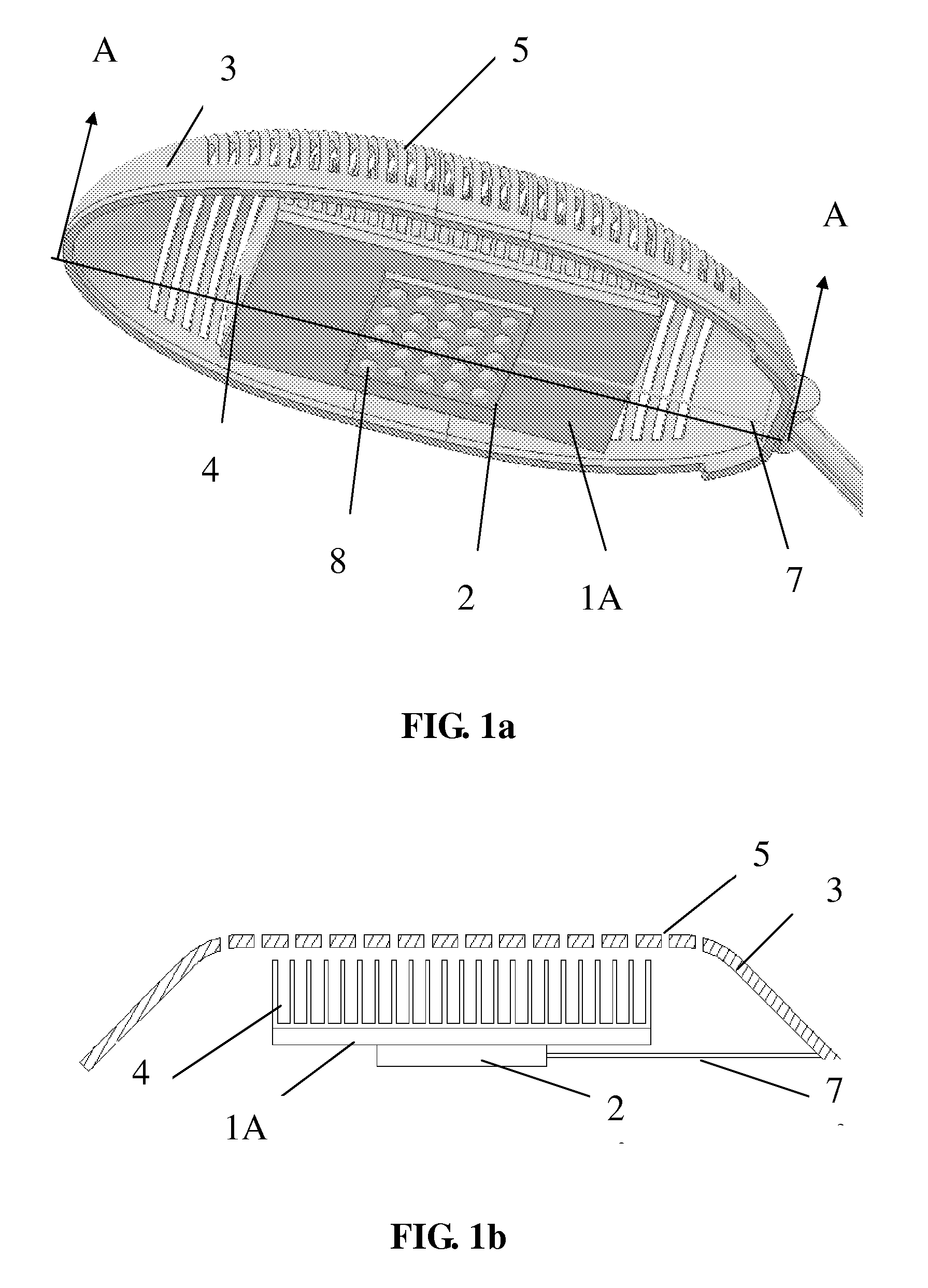
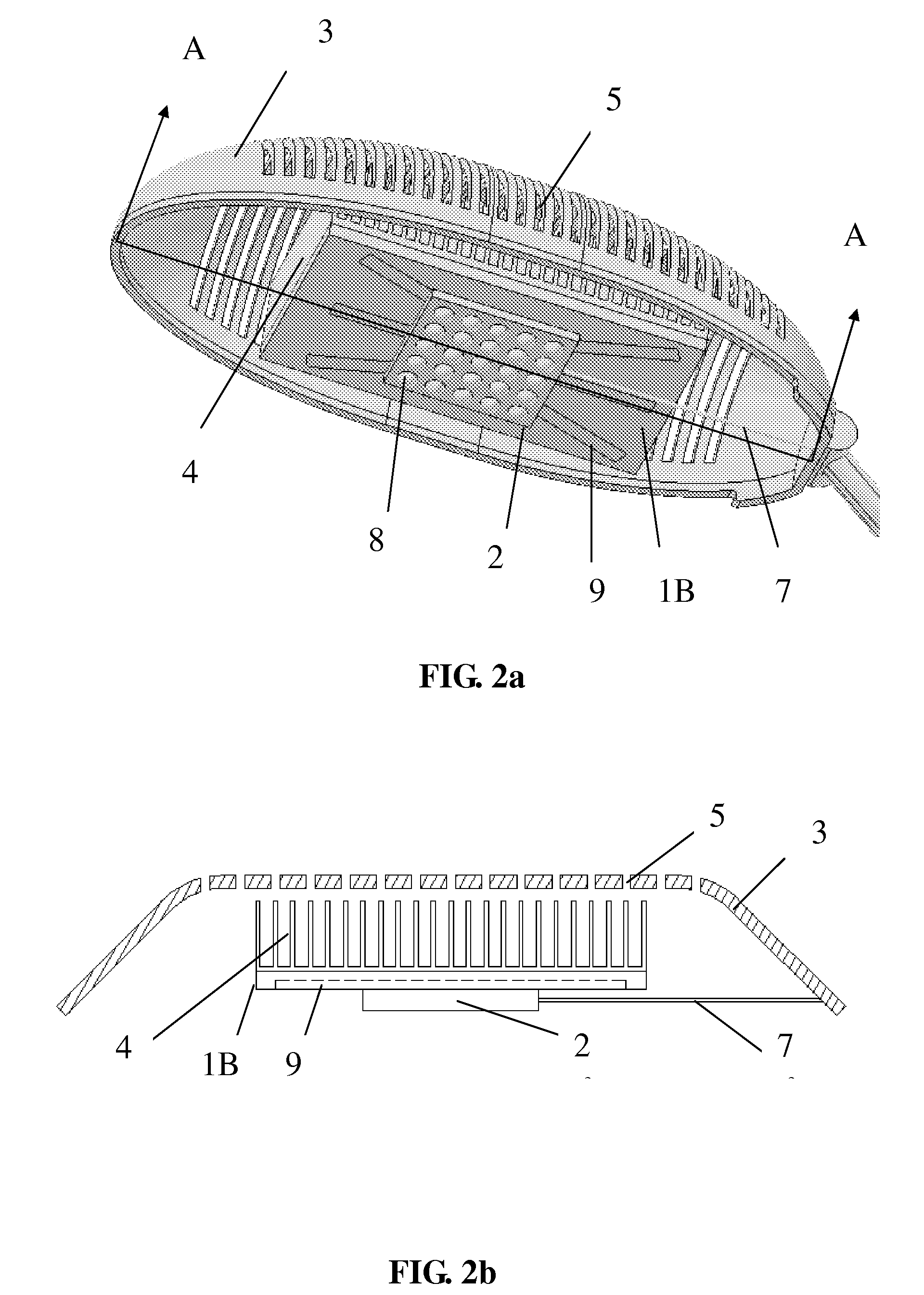
[0014]FIG. 1 shows a first embodiment in which a flat-plate heat pipe 1A is adopted as the plate-type heat spreader. The lamps are exemplified as a lamp set 2 in this invention. Each lamp comprises at least one LED chip mounted on a base substrate. FIG. 1a is the perspective view and FIG. 1b is the cross-sectional view of the A-A section of the device as shown in FIG. 1a. FIG. 2 shows a second embodiment in which a heat-pipe-embedded plate-type heat spreader 1B is adopted as the plate-type heat spreader. FIG. 2a is the perspective view and FIG. 2b is the cross-sectional view of the A-A section of the device as shown in FIG. 2a. In FIG. 2b, the heat pipes 9 are shown in phantom by dotted lines. Each LED lamp 8 in the LED lamp set 2, powered by the electric wire 7, produces light and heat. To keep the LED chips (not shown) in the LED lamp 8 at low temperature, the base (i.e., the major heat dissipation route) of the LED lamp set 2 is thermally connected to the bottom surface of the fl...


PUM


Abstract

This invention discloses heat dissipation devices for an LED lamp set with a plate-type heat spreader as the core unit. The plate-type heat spreader is either a flat-plate heat pipe or a metal plate embedded with heat pipes. The high-power LED lamps are thermally connected to the bottom surface of the heat spreader so that the heat generated by the LED lamps is absorbed by the evaporation region of the flat-plate heat pipe or the embedding heat pipes. The heat is spread by internal vapor motion of the working fluid toward different regions of the heat spreader. The top surface of the heat spreader is connected with a finned heat sink, where the heat is delivered to the ambient air. The hot air leaves by buoyancy through the openings on a lamp housing located above the finned heat sink. An alternative design is that the inner surface of the lamp housing is connected with the top surface of the plate-type heat spreader, with the heat dissipated out at the surface of the housing by natural convection.

Description

RELATED APPLICATIONS [0001] The present application is based on, and claims priority from, Taiwan Application Number 094136258 filed on Oct. 18, 2005 and Taiwan Application Number 095100797 filed on Jan. 9, 2006. The disclosures of which are hereby incorporated by reference herein in its entirety. BACKGROUND OF THE INVENTION [0002] (1) Field of the Invention [0003] This invention relates to heat dissipation of light-emitting diode (LED) lamps. [0004] (2) Brief Description of Related Art [0005] The high power LED light devices produce considerable amount of heat, which may cause performance degrade or even damage if the heat is not removed from the LED chips efficiently. In an LED light device, the core is an LED chip mounted on a substrate. A transparent top covering the LED chip serves as a lens for modifying the direction of the emitted light. Although there are many different designs, the major heat dissipation route for the heat produced by the LED chip usually is managed throug...

Claims


Application Information

Patent Timeline
IPC IPC(8): F21V29/00
CPCF21K9/00F21V29/004F21V29/006F21W2131/103F21Y2101/02F21V29/83Y10S362/80F21V29/507F21V29/763F21V29/80F28D15/0233F21V29/51F21V29/74F21Y2115/10
Inventor WONG, SHWIN-CHUNG
Owner NATIONAL TSING HUA UNIVERSITY
Why Eureka
Try Eureka