
Indwelling heat exchange heat pipe catheter and method of using same

Inactive Publication Date: 2003-03-11
ZOLL CIRCULATION
View PDF61 Cites 107 Cited by
  • Summary
  • Abstract
  • Description
  • Claims
  • Application Information

AI Technical Summary

Benefits of technology

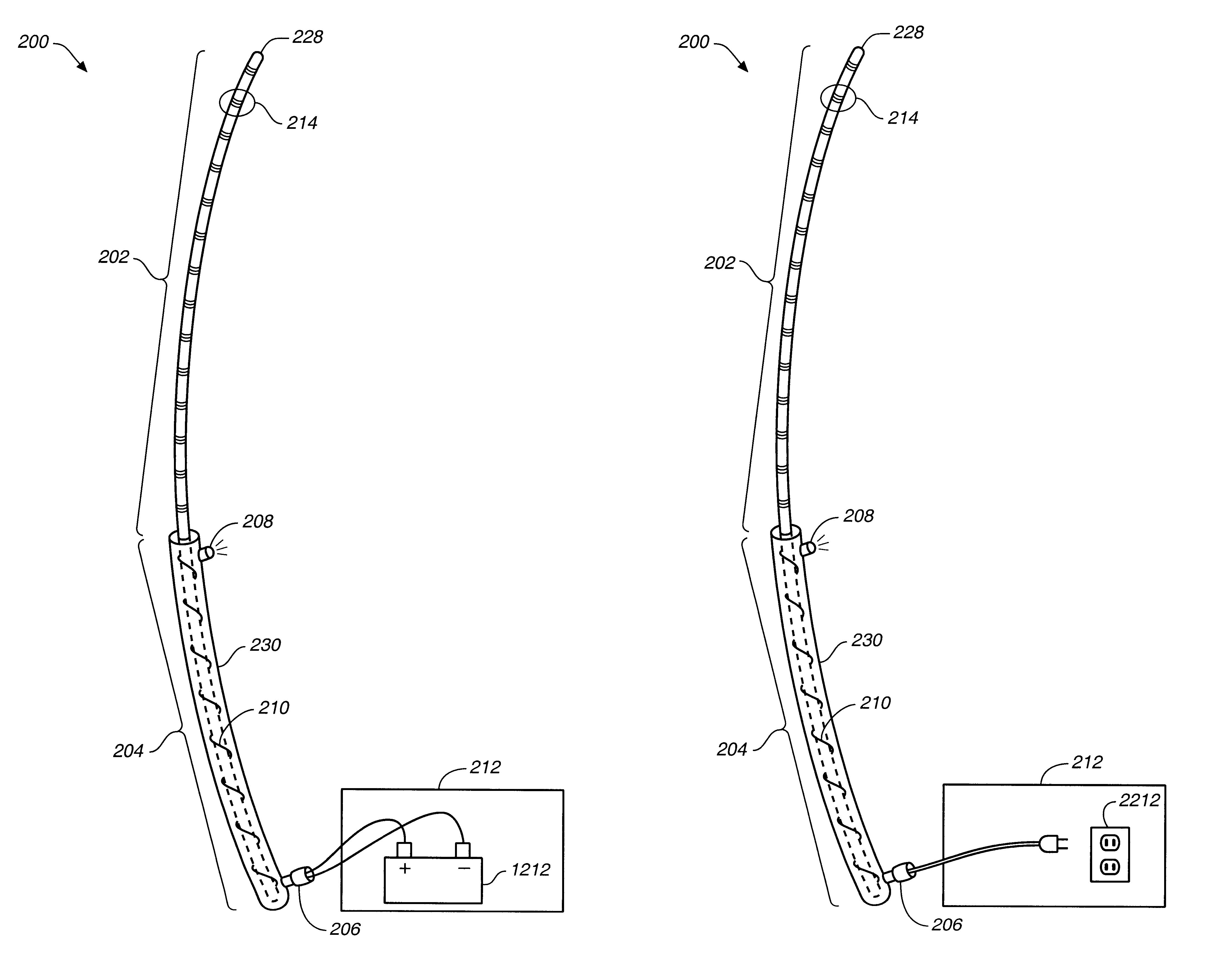
The second portion of the invention provides the cooling capacity which is the driving force for energy transfer of the heat pipe. The heat pipe catheter design described above lends itself to be coupled to many types of cooling sources. Its high efficiency could justify jacketing the heat sink portion with conventional liquid cooling systems such as COOLGARD.TM. (U.S. patent app. Ser. No. 09 / 220,897, filed on Dec. 24, 1998, entitled "Cooling System for Indwelling Heat Exchange Catheter") available from Alsius Corporation in Irvine, Calif. However, its operational characteristics make it unique in that "cold" applied to the heat sink portion makes it work.
A second cold source is based on bottled liquid / gas. In this aspect, the heat sink portion of the catheter is jacketed (enveloped in a manifold) and is coupled to a canister of bottled gas. Preferably, this gas is inert and not harmful, such as CO2. If this CO2 is bottled in a liquid form, it can be released in a metered fashion in the form of a very cold gas vapor. This cold gas being a product of the phase change process. A metering device could be used as a throttle to control the temperature of the heat sink portion of the catheter. The compactness of the bottle and the gas being coupled to the catheter via a hose eliminates having a heavy mechanism attached directly to the catheter. Thus the cannister can be controlled with a control valve and a metered vaporization orifice coupled to at least one hose.
In accordance with the invention there is provided a new and improved method for effecting heat exchange with at least a portion of a body of a patient. The method including inserting a flexible heat pipe heat exchange catheter into a blood vessel of the patient, wherein the heat pipe heat exchange catheter includes an indwelling heat exchange region and an ex vivo heat load dissipater or collector region, and thermally coupling a temperature control module to the ex vivo heat load dissipater or collector region. The method thereby drives a heat exchange interaction between the indwelling heat exchange region and the portion of the body.

Problems solved by technology

Some of the disadvantages of systemic hypothermia include cardiac arrhythmia, pulmonary edema and coagulopathies.
Systemic hypothermia also results in hypotension and various immunodeficiencies.
The systemic approach is not always advantageous when the beneficial effects are desired locally at the focus of the operative procedure and only the disadvantages of hypothermia are felt throughout the remainder of the body.
However Fletcher does not teach a catheter with flexible bellows to allow for insertion into the human bloodstream.
Nor does Fletcher disclose a catheter which can be used in the ambulatory setting.
Topical cooling is slow and labor intensive.
Topical cooling does not always accomplish core cooling as desired.
The flow of cooled blood to the brain reduces the temperature of the brain thereby resulting in cerebral hypothermia.

Method used


Image

  • Indwelling heat exchange heat pipe catheter and method of using same
  • Indwelling heat exchange heat pipe catheter and method of using same
  • Indwelling heat exchange heat pipe catheter and method of using same

Examples


Embodiment Construction

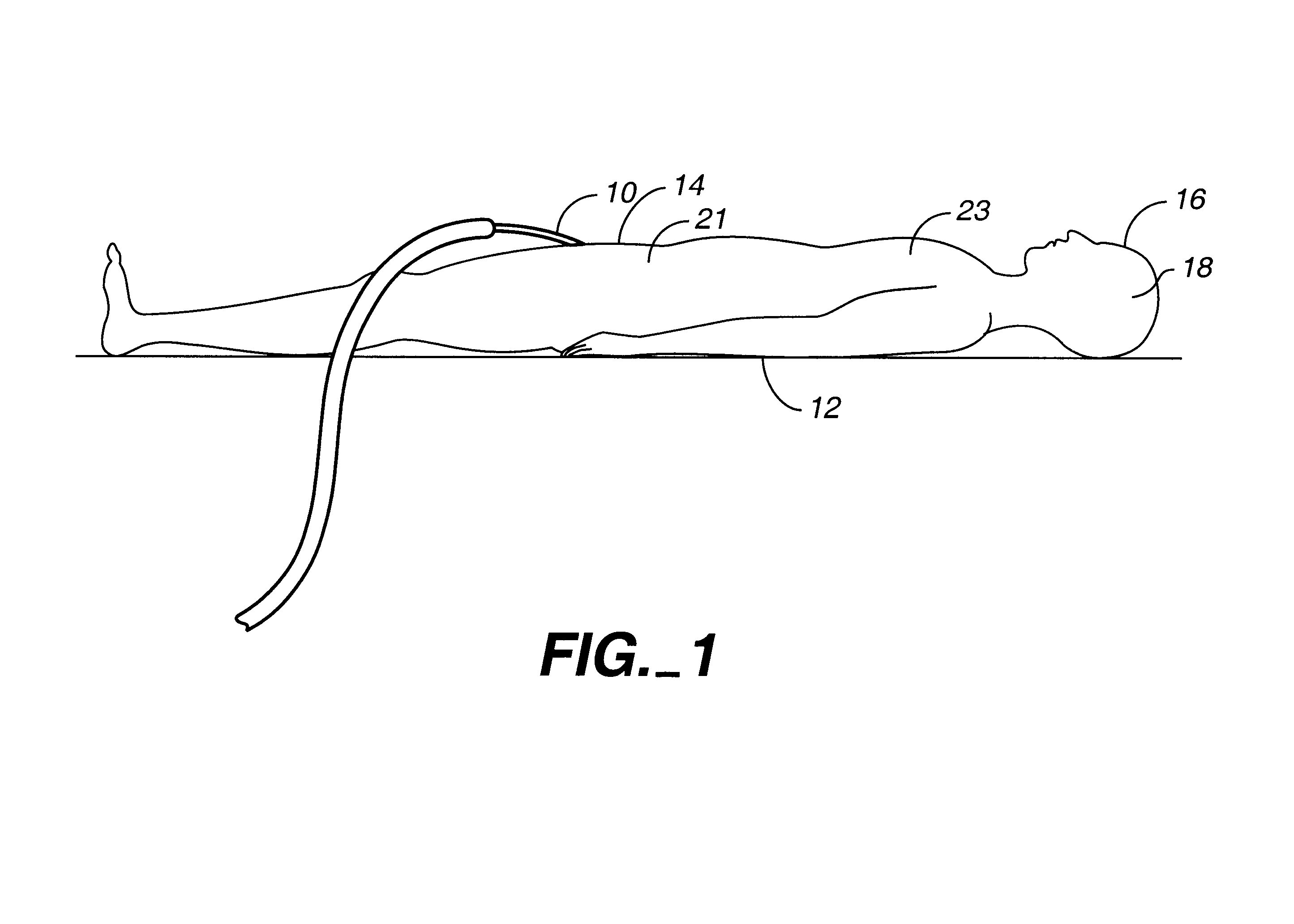
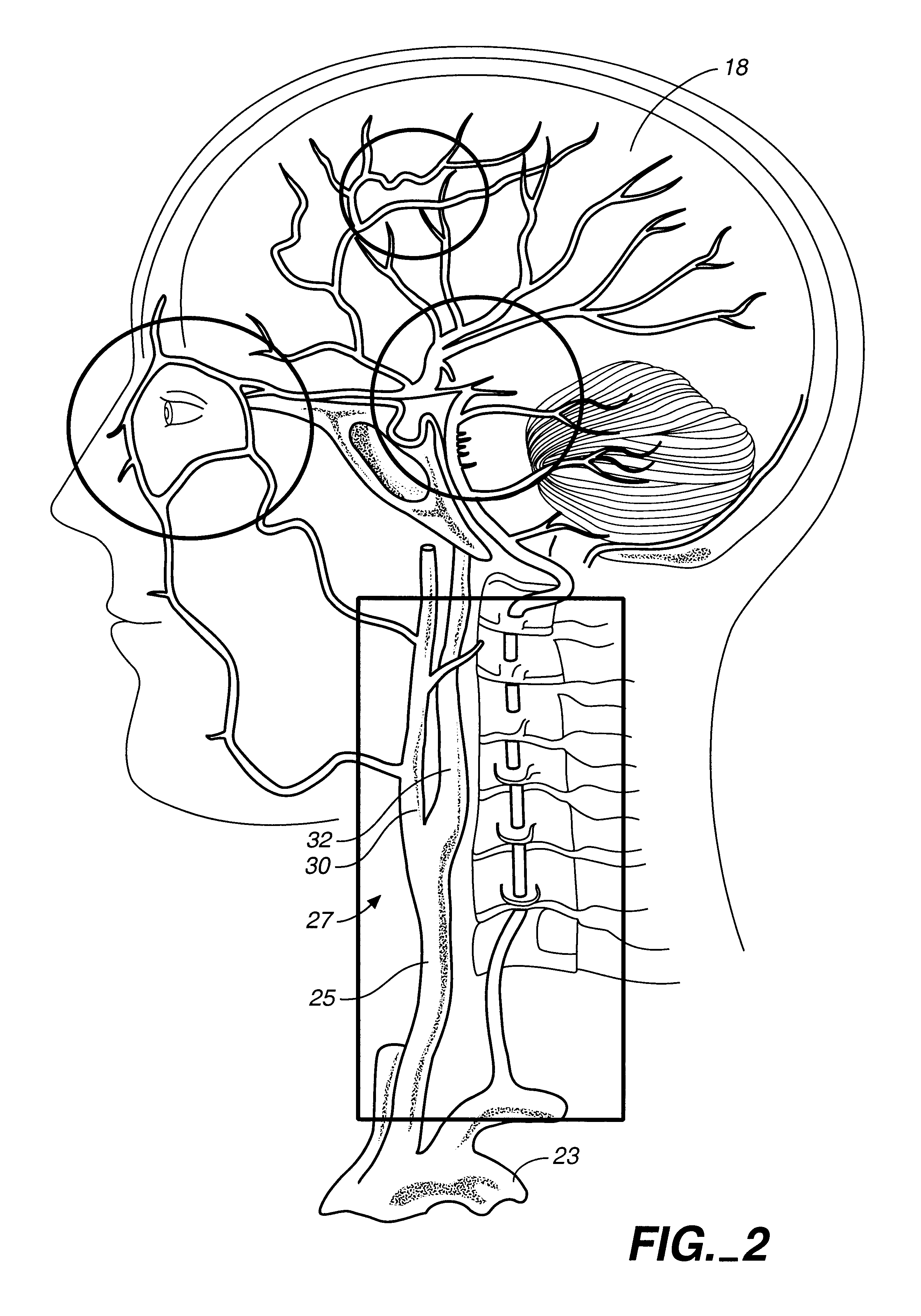
A heat exchange catheter is illustrated in FIG. 1 and designated generally by the reference numeral 10. The catheter 10 is operatively disposed with respect to a body 12 of a patient having a groin 14, a head 16, and a brain 18. More specifically, the catheter 10 can be inserted percutaneously through a puncture or surgical cut down at the groin 14, and into the femoral artery 21. Following this initial introduction, the catheter 10 can be moved through the femoral artery 21 and the aortic arch 23, into the common carotid artery 25 best illustrated in FIG. 2. This common carotid artery 25 divides at a carotid branch 27 into an external carotid artery 30, which primarily supplies blood 31 to the face of the patient, and an internal carotid artery 32, which primarily supplies blood to the brain 18 of the patient.

In the concept of this invention, the brain 18 is merely representative of a portion of the body 12 of the patient, and the arteries 21, 25, 30 and 32 are merely representativ...


PUM


Abstract

A catheter is adapted to exchange heat with a body fluid, such as blood, flowing in a body conduit, such as a blood vessel. The catheter includes a shaft with a heat exchange region disposed at its distal end. This region may include at least one balloon which is adapted to receive a remotely cooled heat exchange fluid preferably flowing in a direction counter to that of the body fluid. Embodiments including multiple balloons enhance the surface area of contact, and the mixing of both the heat exchange and the body fluid. The catheter can be positioned to produce hypothermia in a selective area of the body without cooling the entire body system. It is of particular advantage in brain surgeries where stroke, trauma or cryogenic tumors can best be addressed under hypothermic conditions. Heat pipe technology can be used to form a heat pipe heat exchange catheter. The heat pipe heat exchange catheter includes metallic bellows which allow for flexibility. The temperature control source can be portable to enable the heat pipe heat exchange catheter to be used in the ambulatory environment.

Description

1. Field of the InventionThis invention relates generally to apparatus and methods for producing heat exchange with body tissue, and more specifically to methods and apparatus for the initiation of hypothermic treatment of a body fluid in a body conduit or maintaining normothermia within the body conduit.2. Discussion of the Prior ArtMany of the advantages of hypothermia, as well as maintaining normothermia, are well known. By way of example, it has been found particularly desirable to lower the temperature of body tissue in order to reduce the metabolism of the body. In stroke and several other pathological conditions, hypothermia also reduces the permeability of the blood / brain barrier. It inhibits release of damaging neurotransmitters and also inhibits calcium-mediated effects. Hypothermia inhibits brain edema and lowers intracranial pressure.In the past, hypothermic treatment has been addressed systemically, meaning that the overall temperature of the entire body has been lowere...

Claims


Application Information

Patent Timeline
IPC IPC(8): A61F7/12A61M25/10A61F2/958A61F7/00
CPCA61F7/12A61F7/123A61M25/1011A61F2007/126A61F2007/0076
Inventor NODA, WAYNEEVANS, SCOTTJONES, MIKE
Owner ZOLL CIRCULATION
Learn More