Method and apparatus for treating high pressure particulate material
Inactive Publication Date: 2006-02-07
FOSTER WHEELER ENERGIA OY
12 Cites 48 Cited by
AI-Extracted Technical Summary
Problems solved by technology
Another drawback in this conveyor system is clogging of the conveyor line at its sharp bends, especially if the ash temperature decreases close to the dew point temperature of the carrier gas.
This results, however, in a high consumption of the carrier gas and thus, increases the energy consumption substantially.
In addition, the high flow rate can cause strong erosion, especially at the bends of the line where the f...
Method used
[0052]It is possible to arrange means 16 for the introduction of fluidizing gas, e.g., air, at the bottom of the supply vessel 10. This can prevent the clogging of the lower part of the collecting vessel 30 deriving from the arching of the ash. Further, fluidizing air can be mixed in the carrier gas used in the conveyance, to reduce its dew point. Thus, the clogging of the conveyor line due to moistening as the result of the ash cooling can be prevented.
[0054]The ash conveyor line 20 ends in the collecting vessel 30, to which a discharge conduit 50 for carrier gas is attached. The conve...
Benefits of technology
[0009]It is an object of the present invention to provide a method and an apparatus for tr...
Abstract
An apparatus for pneumatically conveying particulate material containing reaction products of a high pressure reactor from a supply vessel at a pressure of at least two bar to a receiving vessel at a considerably lower pressure. The apparatus includes a conveyor line attached to the supply vessel, a collecting vessel between the conveyor line and the receiving vessel, the collecting vessel including (i) a discharge conduit for the carrier gas, (ii) a device for controlling the discharge velocity of the carrier gas from the collecting vessel, and (iii) a device for controlling the pressure of the material collected in the collecting vessel, and a device for conveying the material directly from the collecting vessel to the receiving vessel essentially at the same pressure as is prevailing in the receiving vessel.
Application Domain
Fluidized bed combustionBulk conveyors +3
Technology Topic
EngineeringHigh pressure +3
Image
Examples
- Experimental program(1)
Example
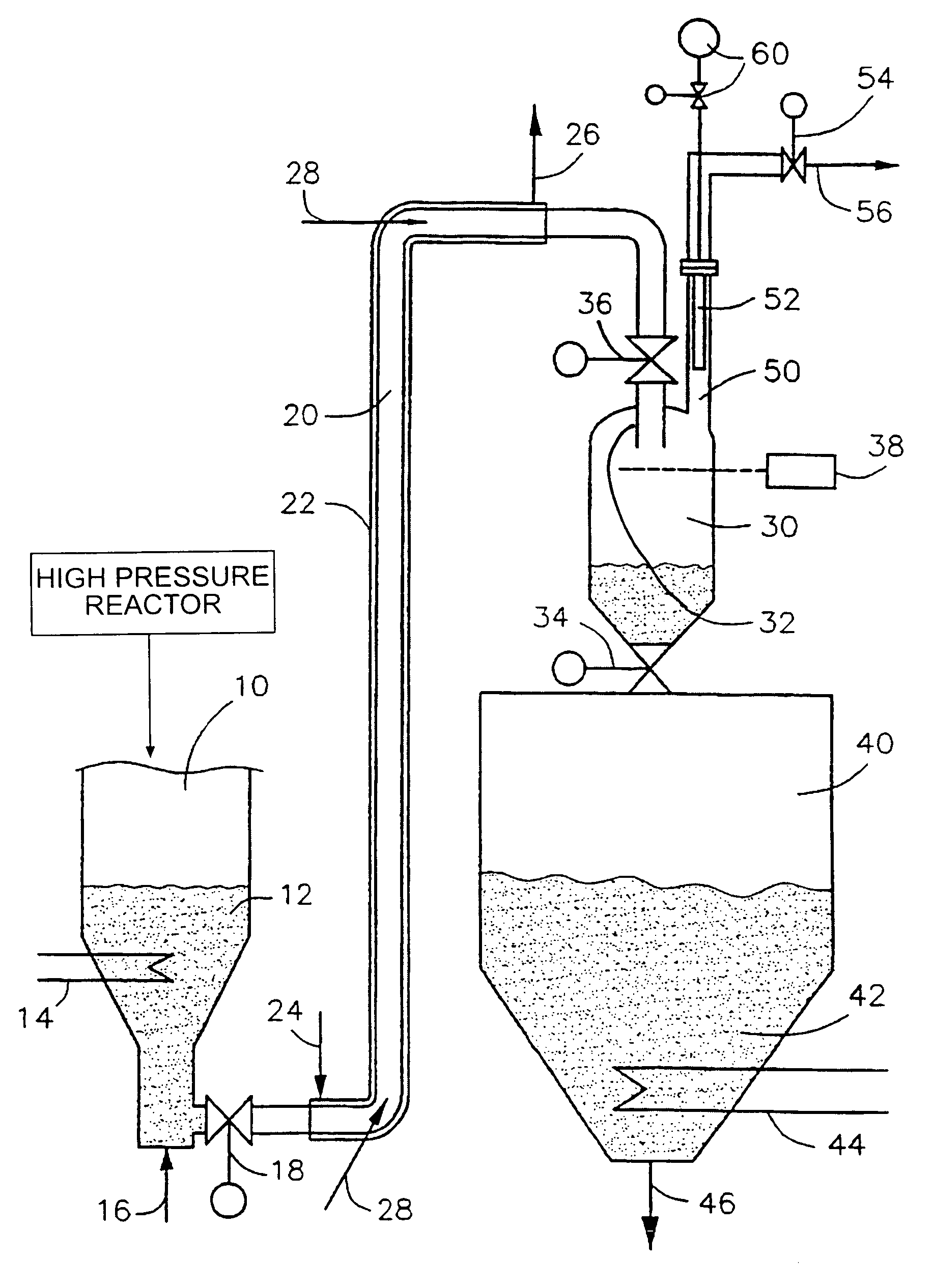
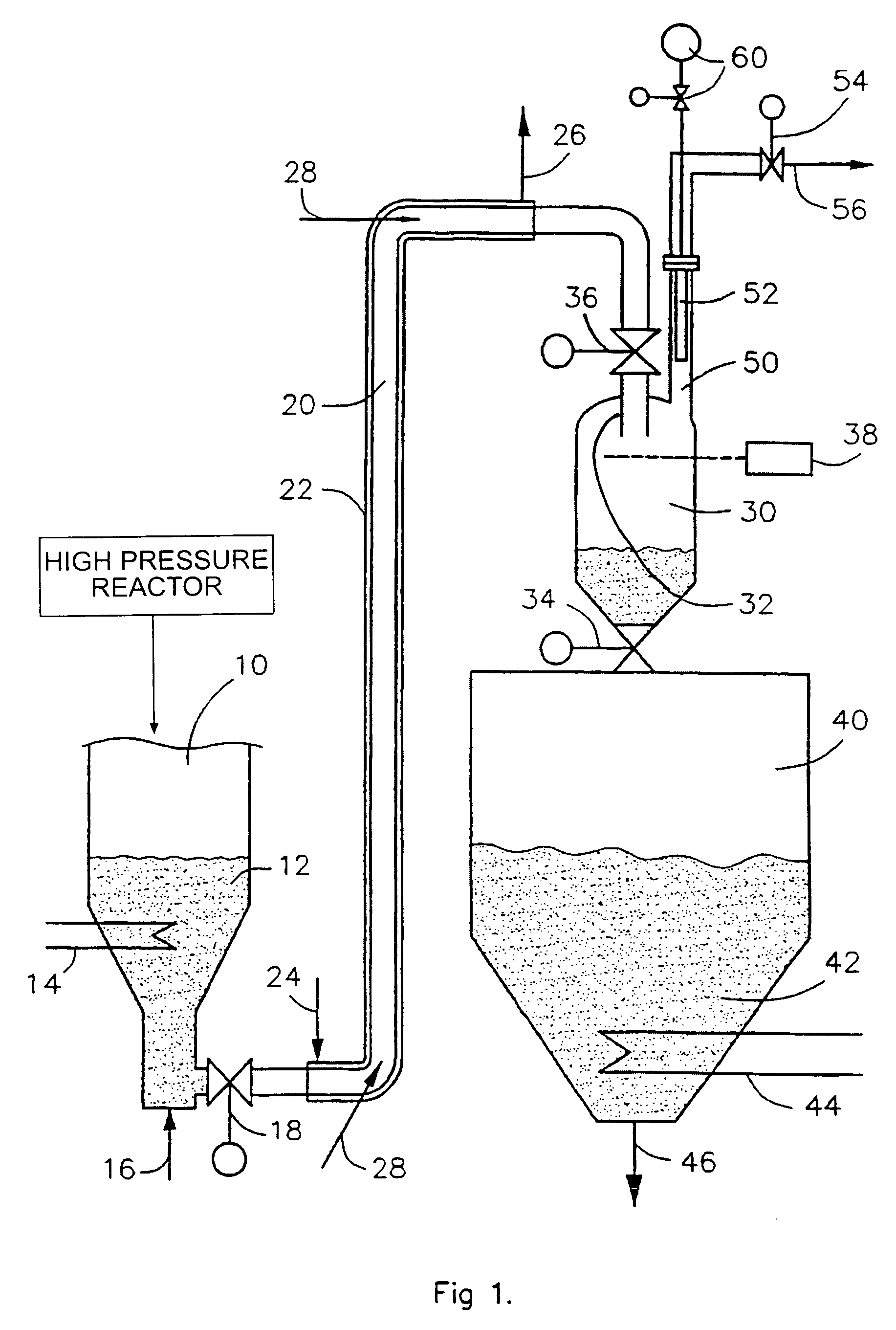
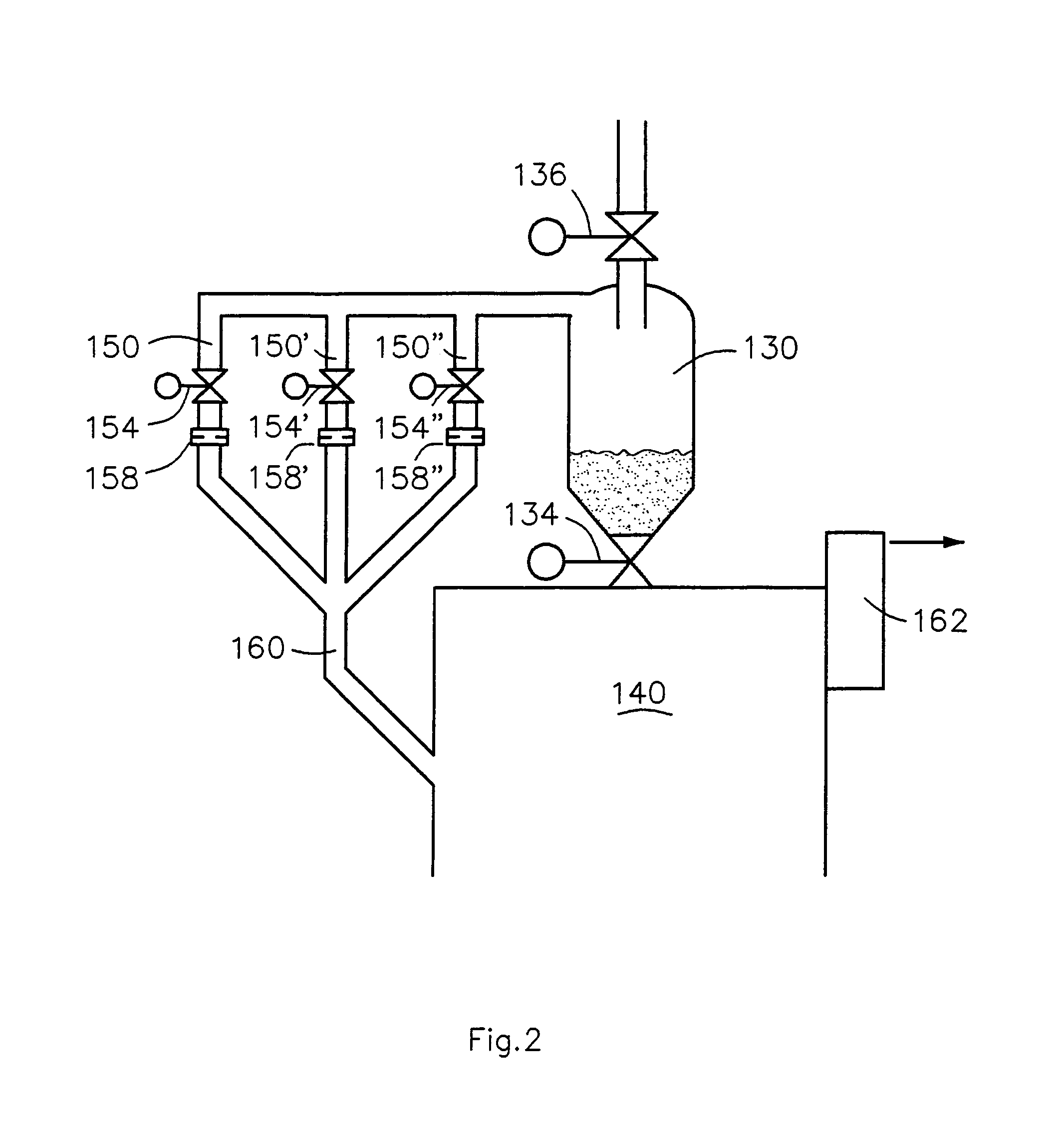
[0047]FIG. 1 illustrates an ash conveying system according to a first preferred embodiment of the present invention, in which a supply vessel 10, an ash conveyor line 20 and a receiving vessel 40 can be similar to those even in other preferred embodiments. The various embodiments differ from each other mainly in how the carrier gas discharge from a collecting vessel 30 and the pressure reduction of the collected material are arranged.
[0048]The invention is characterized in that particulate material containing reaction products of a reactor is conveyed pneumatically from a supply vessel 10 at a pressure of at least 2 bar, typically at 6–20 bar, to a receiving vessel 40, e.g., at atmospheric pressure, using the gas exiting the reactor as a carrier gas. When applying the invention, the volume of the supply vessel is typically larger than the volume of the conveyor line and it can be assumed that the pressure of the supply vessel 10 is constant.
[0049]The supply vessel 10 can consist, e.g., of a bottom part of a filter for fly ash removal from a high pressure fluidized bed reactor or it can be a part of the removal system for bottom ash from a fluidized bed reactor. In the former case, the ash 12 collected in the supply vessel 10 is powdered, compressible fly ash, whereas in the latter case, the ash could be coarse. The quality of the ash to be conveyed has to be considered when choosing the embodiment and the method, by which the system according to the present invention is applied.
[0050]In the supply vessel 10, the ash temperature is typically 400–1200° C. and for precooling the ash, the vessel 10 can be provided with heat exchange surfaces 14, e.g., heat exchange pipes, in which water or steam circulates.
[0051]The ash is conveyed in a tubular conveyor line 20, in which a heat exchange surface could be arranged, e.g., a sleeve 22 covering the line at least partly and having means 24, 26 for the recirculation of a heat exchange medium, e.g., water or steam. By the heat exchange surfaces 22, the ash temperature can be reduced, e.g., to 150–300° C.
[0052]It is possible to arrange means 16 for the introduction of fluidizing gas, e.g., air, at the bottom of the supply vessel 10. This can prevent the clogging of the lower part of the collecting vessel 30 deriving from the arching of the ash. Further, fluidizing air can be mixed in the carrier gas used in the conveyance, to reduce its dew point. Thus, the clogging of the conveyor line due to moistening as the result of the ash cooling can be prevented.
[0053]In FIG. 1, the conveyor line 20 starts below the supply vessel 10, turns upwards after the horizontal section and leads again horizontally above the collecting vessel 30. In practice, the conveyor line can consist of parts with any desired position. To avoid the clogging of the line, it could be occasionally or continuously necessary to add small quantities of carrier gas 28, e.g., air, to some points of the line, especially to the bent sections.
[0054]The ash conveyor line 20 ends in the collecting vessel 30, to which a discharge conduit 50 for carrier gas is attached. The conveyor line 20 is preferably formed of an extension part 32 extending slightly into the collecting vessel and directing the ash towards the bottom of the collecting vessel 30, thus reducing the probability of the ash being entrained with the gas to the discharge conduit 50. The collecting vessel 30 is also formed so as to reduce the speed of the carrier gas essentially when flowing from the extension part 32 of the conveyor line 20 to the collecting vessel. Thus, the collecting vessel serves as a settling chamber for ash, separating a substantial part of the ash conveyed by the carrier gas.
[0055]In the embodiment according to FIG. 1, the discharge conduit 50 is provided with a filter 52 and a control valve 54 for controlling the flow rate of the discharged carrier gas 56. The discharge conduit 50 leads preferably to the open air or to a space essentially at atmospheric pressure. If the pressure of the receiving vessel differs from the atmospheric pressure, it is preferably to draw the discharge conduit 50 to a space essentially at the same pressure as that of the receiving vessel 40.
[0056]As ash can be entrained with the carrier gas to filter 52, the filter 52 is provided with a system 60 for cleaning the filter 52 by giving intermittent gas pulses to the clean side thereof.
[0057]In the embodiment according to FIG. 1, the collecting vessel 30 is arranged immediately above the receiving vessel 40. The collecting vessel 30 is separated from the receiving vessel 40 by a gas tight valve 34. There is also a gas tight valve 36 between the collecting vessel 30 and the conveyor line 20.
[0058]The present invention is characterized in that the gas discharge speed is adjusted by a control valve 54 so as to convey ash in the line 20 as a dense suspension, the flow rate of the carrier gas being less than 5 m/s. Thus, the erosion and consumption of carrier gas caused by the conveyance are relatively insignificant. Valve 34 is shut and valve 36 is open during the conveyance. It is to be noted that valve 36 is not used for controlling the conveying speed of the ash or for stopping thereof.
[0059]In the technical solution according to FIG. 1, a valve 18 is also arranged between the supply vessel 10 and the conveyor line 20. The system may include such a valve and possibly even other valves not marked in the figure, as they do not have any significance from the viewpoint of the present invention. Valve 18 could be needed, e.g., when maintaining the system, but in normal operation, the valve is open.
[0060]When the level transmitter 38 attached to the collecting vessel 30 indicates that the collecting vessel 30 is about to get filled, the ash conveyance is stopped. The carrier gas flow is stopped by shutting valve 54. When the ash conveyance is stopped, valve 36 is shut. After this, valve 54 is reopened and the pressure of the collecting vessel is allowed to fall so that it is essentially the same as the pressure of the receiving vessel and the ash can fall down into the receiving vessel by opening the valve 34.
[0061]To restart the ash conveyance, valve 34 is shut, valve 36 is opened and the ash flow rate is adjusted by valve 54 to a desired value. To protect valve 36, it could be necessary to raise the pressure of the collecting vessel essentially to the same level as that of the supply vessel 10. This can preferably be performed by using the same system 60 that produces clean pulses for the filter 52 of the discharge conduit 50. Simultaneously, the filter 52 is also cleaned from ash possibly collected on its surface at the preceding filling stage of the collecting vessel 30. The receiving vessel 40 can be provided with heat exchange surfaces 44 for the final cooling of the ash as well as with an opening for ash discharge 46 in the bottom of the vessel 40.
[0062]The ash conveyance system according to the present invention is preferably used intermittently also between the discharges of the collecting vessel 30 so that the temperature T1 of the ash entering the collecting vessel 30 at the end of the conveyor line 20 and the pressure difference Δp between the supply vessel 10 and the collecting vessel 30 are monitored. When the temperature T1 or the pressure difference Δp is not within the predetermined limits, the discharge of carrier gas and the ash conveyance are stopped by valve 54. Sometimes, it could be sufficient to perform the ash conveyance in a predetermined way intermittently. The ash conveyance can also be stopped when it is detected that the volume of ash in the supply vessel 10 falls below a predetermined level.
[0063]FIG. 2 schematically illustrates the outlet end of the ash conveying system according to a second preferred embodiment of the present invention. There, the collecting vessel 130, receiving vessel 140, valves 136 and 134 and the parts not shown in the figure are similar to those in the embodiment according to FIG. 1. The operation principle of this embodiment is also similar to that of the embodiment according to FIG. 1.
[0064]The second preferred embodiment according to FIG. 2 differs from the first preferred embodiment according to FIG. 1 in that the discharge conduit for carrier gas is in communication with the receiving vessel 140. Thus, the ash entrained with the carrier gas is also led to the receiving vessel 140. Naturally, when using the second preferred embodiment according to FIG. 2, the receiving vessel 140 has to be provided with a discharge conduit for gas, e.g., to open the open air, and a filter 162 preventing the ash from being entrained out with the gas.
[0065]In the embodiment according to FIG. 2, the discharge conduit is divided into three parallel conduits 150, 150′, 150″ joining to one conduit 160 before reaching the receiving vessel 140. As the ash entrained with the carrier gas could deteriorate the operational condition of the control valve, the control valve 54 of FIG. 1 has been replaced by steadier shut-off valves 154, 154′, 154″ and critical openings 158, 158′, 158″, like or unlike each other, restricting the gas flow. Naturally, the number of parallel conduits can also be different from three.
[0066]In the embodiment according to FIG. 2, the ash conveying speed can be controlled by opening a necessary number of the shut-off valves 154, 154′, 154″. If ash is conveyed periodically, the extent of the conveyance can also be regulated by changing the duration of the periods, whereby it is not necessary to have more than one discharge conduit, shut-off valve and critical opening.
[0067]FIG. 3 schematically illustrates the outlet end of the ash conveying system according to a third preferred embodiment of the present invention. In this embodiment, the collecting vessel 230 at the end of the conveyor line is narrow and high, even though its diameter is larger than that of the conveyor line. The proportion of the height of the collecting vessel to its diameter is preferably at least five, most preferably at least ten.
[0068]When conveying ash, an ash column is maintained in the collecting vessel 230 extending preferably at least to the center part of the vessel 230. In the embodiment according to the figure, the ash flow is regulated by a discharge conduit 250 for carrier gas attached to the center part of the collecting vessel 230, in which conduit, the volume of carrier gas 256 can be regulated by a valve 254. At the end of the discharge conduit 250 closest to the collecting vessel 230 is arranged a filter 252 preventing the ash from entering the discharge conduit 250. When the filter 252 is disposed according to the figure inside the ash column flowing downwards, the moving ash simultaneously cleans the outer surface of the filter 252 and prevents the filter 252 from being clogged up.
[0069]Another advantage gained by arranging the first end of the discharge conduit 250 in the area of the ash column is that the portion of the ash column above the joining point of the discharge conduit 250 also acts as a restrictor for the carrier gas flow. Thus, the ash conveyance is partly self-adjusting as the high ash column slows down the gas flow and reduces or even stops the ash conveyance, when the collecting vessel 230 is about to get filled.
[0070]The discharge conduit 250 can also be arranged in the upper part of the collecting vessel 230, whereby it functions in the same way as the discharge conduit 50 according to the first preferred embodiment in FIG. 1. It is also possible to connect the discharge conduit 250 to the lower part of the collecting vessel 230, whereby the flow regulating effect of the ash column is at its highest.
[0071]FIG. 3 also shows another discharge conduit 260 for gas provided with a filter 262 and a control valve 264. The purpose of the discharge conduit 260 is to let the carrier gas 266, discharged from the lower part of the collecting vessel 230, enter the open air without any particular obstruction, i.e., during the ash conveyance, valve 264 does not essentially limit the gas flow. Thus, the lower part of the collecting vessel 230 reaches the atmospheric pressure and the ash 272 can be easily removed from the lower part of the collecting vessel 230 to the receiving vessel (not shown), e.g., by using a rotary feeder 270. The discharge apparatus for ash at the bottom of the collecting vessel 230 can also be of another type, e.g., a conveyor screw or an L-valve. Pressure adjusting in the collecting vessel 230 can also be practiced in many steps, whereby more than the mentioned two discharge conduits 250 for gas are disposed in the collecting vessel 230.
[0072]FIG. 3 also shows a level transmitter 238 provided in the upper part of the collecting vessel 230, and an apparatus 258 for feeding high pressure cleaning pulses to the filters 252 and 262. The collecting vessel 230 can also be used so that the upper surface of the ash column is continuously maintained at a desired predetermined level by using a rotary feeder 270. Another possibility is to use a rotary feeder intermittently, whereby the ash level remains within certain predetermined limits.
[0073]When starting the ash treatment system according to FIG. 3, e.g., sand can be fed to the collecting vessel 230 through a separate conduit not shown in FIG. 3, whereby a sand column restricts the gas flow at the starting stage.
[0074]The invention has just been described in connection with embodiments that are presently considered to be the most preferable. It must, however, be understood that the invention is not limited to these embodiments. Rather, it covers a number of other arrangements within the scope of invention determined by the claims below. For example, a plurality of ash conveyor lines can lead into the same collecting vessel.
PUM


Description & Claims & Application Information
We can also present the details of the Description, Claims and Application information to help users get a comprehensive understanding of the technical details of the patent, such as background art, summary of invention, brief description of drawings, description of embodiments, and other original content. On the other hand, users can also determine the specific scope of protection of the technology through the list of claims; as well as understand the changes in the life cycle of the technology with the presentation of the patent timeline. Login to view more.