Optical sash sensing system for fume hoods

a sensing system and optical sash technology, applied in ventilation systems, heating types, stoves or ranges, etc., can solve the problems of insufficient information about the absolute position of the sash, the danger of contamination, and the debate over what types of sensing

Inactive Publication Date: 2006-02-07
TRIATEK HLDG
View PDF9 Cites 63 Cited by
  • Summary
  • Abstract
  • Description
  • Claims
  • Application Information

AI Technical Summary

Problems solved by technology

Dangers of contamination exist, however, with respect to periods of time when the sashes of a respective fume hood are left open and there is much debate over the minimum face velocities that must be maintained for the fume hood user to be kept “safe”.
Further, there is also much debate with respect to what types of sensing mechanisms should be used to keep a user safe such as airflow measurement or sash sensing or a combination of both.
As is noted in these patents, with two or more sashes, absolute position of the sashes is not sufficient information by itself to indicate the open area of the hood.
The problem becomes even more complex where four sashes are mounted on two tracks, which is a very common configuration, or where the hood is being moved both horizontally and vertically.
Although this prior art is preferred over other available technology, such electrical connection methods for sash position sensing are less than optimal, particularly for cases where sensing is to be provided for horizontal sash, combination sash, or walk-in hood types.
Routing the horizontal sash sensor cable presents difficulties related to either the establishment of operative pivot points or mounting a take-up reel for cable movement.
The issues faced include both real and perceived reduced reliability over time due to cable wear, difficulties in installation, and the poor aesthetics of exposed cable that moves in a pendulous manner.
Other issues with conventional technology have been with the thickness of the sensor and magnet bars, given the increasing trends for tighter hood construction and, thus, reduced spacing between sashes from one track to another.
The multiplicity of elements can be cost prohibitive and difficult to maintain.
However, this invention has proved to be impractical in the field, expensive, and not widely used due to the need for using an awkward lever in tandem with the rotary sensor.

Method used


Image

  • Optical sash sensing system for fume hoods
  • Optical sash sensing system for fume hoods
  • Optical sash sensing system for fume hoods

Examples


Embodiment Construction

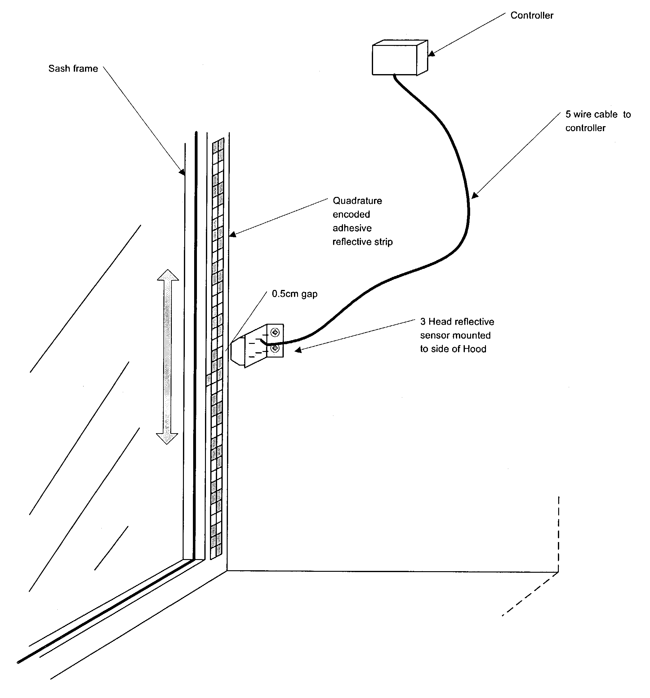
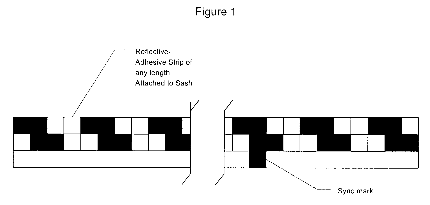
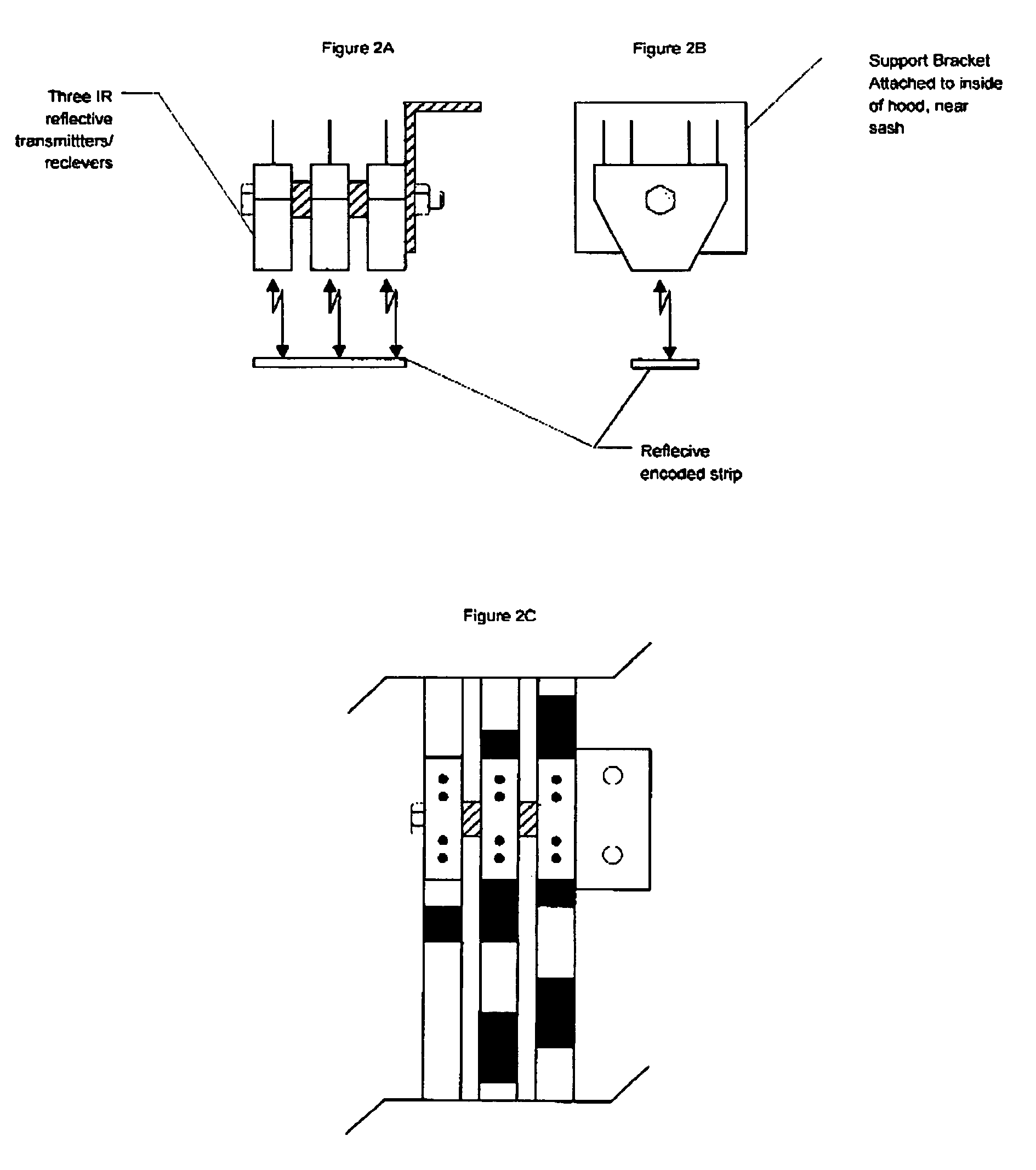
[0017]With reference to FIG. 1 there is shown a condensed reproduction of the typical reflective adhesive tape that is used in this application. The tape is thin in width but has 3 distinct parallel sections or strips to it. On the bottom third of the tape that is depicted horizontally is a white reference strip that runs the length of the sash and is all white except for one black sync mark identified in the drawing which is used as a baseline reference point by the sensing device to count up or down in determining when the sash has moved. The top two-thirds of the tape are the repeated quadrature encoded patterns composed of four offset blocks of black and white that are repeated over the length of the tape. The white (or silver) blocks are reflected back onto the optical sensing device (FIG. 2) which is able to count these quad-blocks with reference to the sync point to determine the absolute value of the sash that has passed it as it is moved up or down to determine airflow adju...


PUM


Abstract

A fume hood optical sash sensing system for controlling the flow of air into a fume hood to maintain a constant face velocity by utilizing an optical sensing device mounted inside the fume hood that can sense the movement of a sash based on repeatable reflexive tape to produce an output control signal that corresponds to sash movement to produce desired airflow into the fume hood. The system includes an optical sensing device with a light source, reflexive tape with a repetitive, quadrature encoded pattern, a smart controller device that receives output control signals from the optical sensing device, and an actuation device capable of receiving the output signal from the controlling device to control the damper device that will result in constant face velocity across the face of the sash.

Description

FIELD OF THE INVENTION[0001]This invention relates to laboratory fume hoods and more specifically to apparatus for detecting the extent to which the sashes of a fume hood are open.BACKGROUND OF THE INVENTION[0002]The use and development of laboratory fume hoods for cutting edge research dealing with everything from bioterrorism to the human genome has resulted in many inventions to handle harmful materials safely and engendered much debate about the best way to control airflow through the fume hood. This debate concerns the capture of contaminants and the prevention of their escape into the surrounding environs where the lives of laboratory researchers, students, teachers, occupants, technicians and other personnel may be threatened. Various types of fume hoods with various types of configurations all utilize various sash mechanisms which promise safety to the user by their closing the sash during their experiments so that an exhaust fan can draw toxic fumes, pathogens and contamina...

Claims


Application Information

Patent Timeline
Patent Type & Authority Patents(United States)
IPC IPC(8): B08B15/02B01L1/00
CPCB01L1/00B08B15/023B01L2200/145
Inventor SCHOLTEN, JEAN H
Owner TRIATEK HLDG
Why Eureka
Try Eureka