Prosthetic annular coupling socket adaptor with adjustable clamp

Inactive Publication Date: 2006-02-07
PROSTHETIC DESIGN
View PDF4 Cites 12 Cited by
  • Summary
  • Abstract
  • Description
  • Claims
  • Application Information

AI Technical Summary

Benefits of technology

[0009]In a first exemplary embodiment of the present invention, a height-adjustable prosthetic coupling is provided that has an annular coupling adapter (pyramid receiver) on one end and a diametrically restrictable tube (tube clamp) on the opposing end, which allows for height (axial) adjustment between the coupling and a prosthetic pylon. The diametrically restrictable tube has an internal depth which accommodates the insertion of a portion of the pylon. Conventional pyramid-receiver tube clamps have a diametrically restrictable tube of a minimal length sufficient to provide enough surface area to securely lock the tube clamp onto the pylon. One reason for minimizing this length is to reduce the material costs for such components. The first exemplary embodiment of the present invention, on the other hand, provides a diametrically restrictable tube having an internal depth which can accommodate more than the minimum length of the pylon necessary for properly securing the pylon to the coupling. In other words, the interior height of the tube is greater than prior art tubes. When the patient requires the overall length between the tube clamp and pylon to be adjusted, the prosthetist “frees up” the diametrically restrictable tube so as to enable movement between the internal surface of the tube and the exterior surface of the pylon. Once the desired overall length is reached, the prosthetist restricts the diametrically restrictable tube and prevents noticeable movement between the pylon and tube; both in the vertical, and in the rotational / axial direction. Thus, the present invention provides for human errors in measuring and provides adjustability to meet the patient's needs and may not require the procurement of a plurality of pylons of varied lengths.
[0010]Likewise, the elements of the first exemplary embodiment may be combined with bushings (or spacers) that fill any potential axial void that may be present in the first exemplary embodiment between the shoulder of the coupling extending radially into the channel of the tube and the longitudinal end-surface of the pylon; resulting in a second exemplary embodiment. The second exemplary embodiment provides a plurality of variable-height axial bushings that are insertable into the tube of the coupling before the pylon is inserted. One or more of these bushings may be inserted to fill any potential void between the coupling and the longitudinal surface of the pylon. Thus, the adjustment of the prosthetic components may be made easier for the prosthetist because the weight of the tube clamp and associated prosthetic components may be pressed onto the pylon without the fear of hampering the measurements surrounding the proper depth of the pylon.
[0013]It is a third aspect of the present invention to provide an adjustable prosthetic coupling comprising a pylon receiving portion having a means for selectively securing a prosthetic pylon therein and, a pyramid receiving portion including a means for selectively securing a prosthetic pyramid thereto, where the means for selectively securing the prosthetic pylon therein includes a plurality of height adjustments between the prosthetic pyramid and the prosthetic pylon, and the means for selectively securing the prosthetic pylon therein enables day-to-day use.
[0014]It is a fourth aspect of the present invention to provide a method for custom fitting prosthetic devices, comprising the steps of: providing a prosthetic coupling device adapted to couple a prosthetic pylon to a second prosthetic limb component, the coupling device having a concavity adapted to interface with a prosthetic pylon, the cavity accommodating various depths of pylon insertion to provide height adjustability with the second prosthetic limb component, the coupling device further being designed for day-to-day use; and, mounting the prosthetic component to the prosthetic pylon so as to provide a secure coupling between the prosthetic component enabling day-to-day use.

Problems solved by technology

Problems sometimes arise when the pylon is ground down or cut, thereby shortening its length beyond that which is required.
Alternatively, if the original pylon is too short, the current state of the art provides no alternative for the prosthetist other than procuring another pylon having a greater length.

Method used


Image

  • Prosthetic annular coupling socket adaptor with adjustable clamp
  • Prosthetic annular coupling socket adaptor with adjustable clamp
  • Prosthetic annular coupling socket adaptor with adjustable clamp

Examples


Embodiment Construction

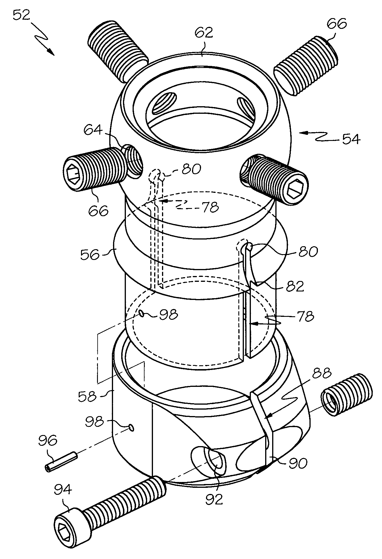
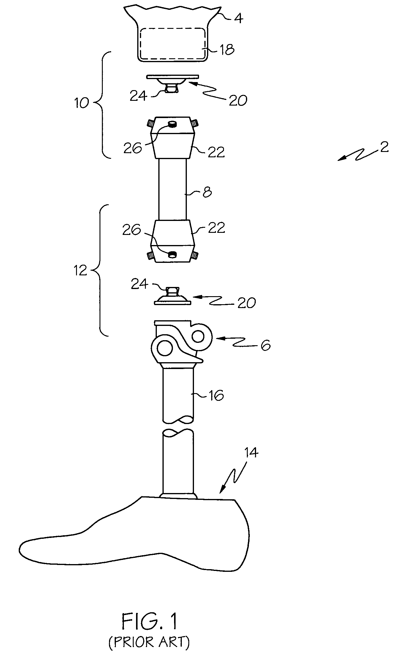
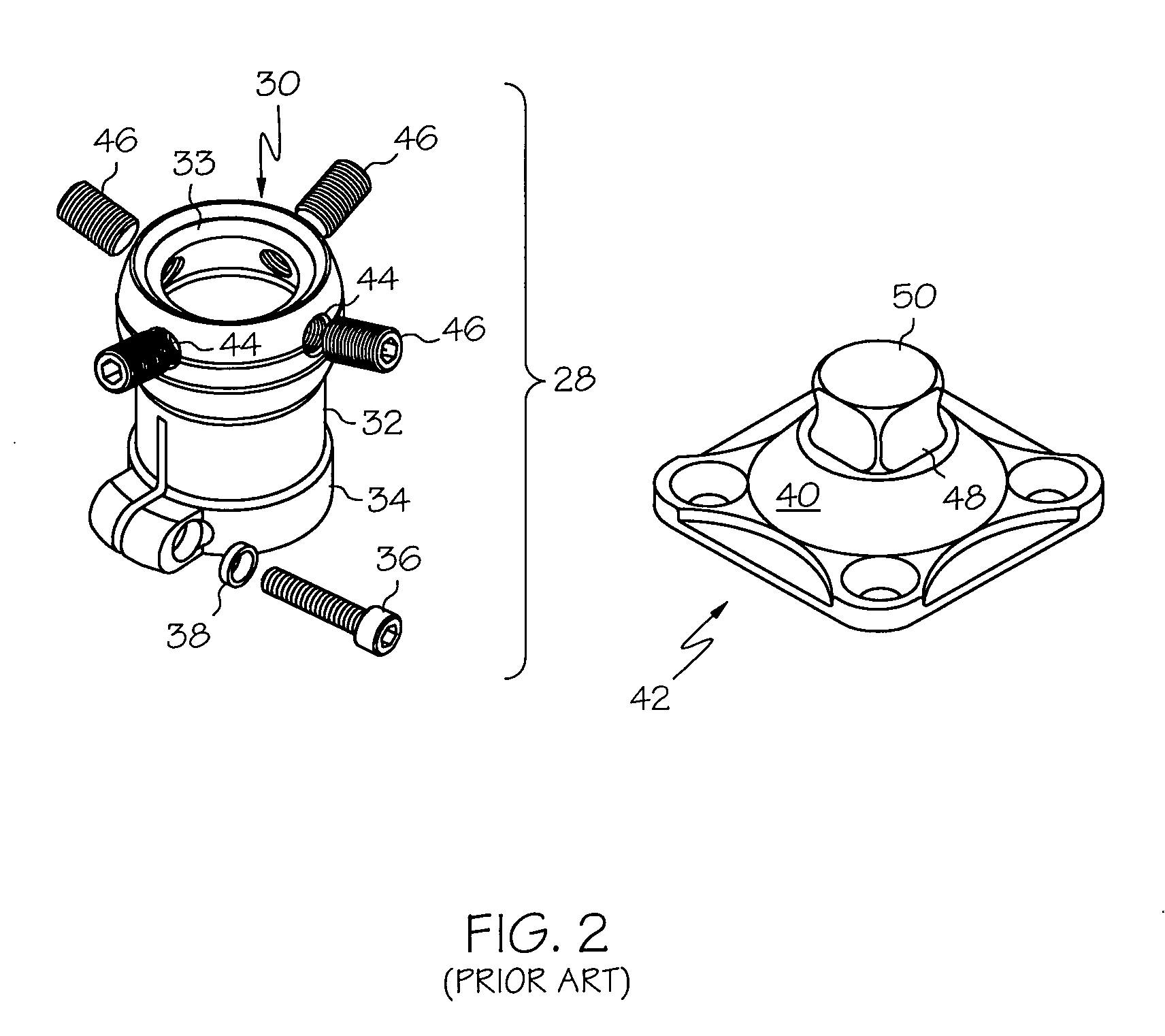
[0024]The exemplary embodiments of the present invention are described and illustrated below as prosthetic limb couplings, for mounting a first prosthetic component to a second pylon component, that include height-adjustable tube clamps for mating with pylon components. The various orientational or positional terms used to describe the elements of the inventions are therefore used according to this frame of reference. Of course, it will be apparent to those of ordinary skill in the art that the preferred embodiments may also be used in combination with one or more prosthetic components to function as a complete prosthetic assembly. In such a case, the orientational or positional terms may be different. However, for clarity and precision, only a single orientational or positional reference will be utilized; and, therefore it will be understood that the positional and orientational terms used to describe the elements of the exemplary embodiments of the present invention are only used ...


PUM


Abstract

A prosthetic coupling comprising an annular coupling adapter having a coupling end and an opposed pylon mounting end, the coupling end including a central bore adapted to receive, and be coupled to a prosthetic limb pyramid component, where the pylon mounting end includes a diametrically restrictable tube with at least two circumferential discontinuities and an axial depth with a predetermined extension greater than a minimum depth required to adequately secure a prosthetic limb pylon component therein, where the predetermined extension provides the prosthetic coupling height adjustability with respect to the prosthetic limb pylon to which it is adapted to be secured. Such prosthetic couplings may be supplemented with bushings inserted within the pylon mounting end to inhibit further pylon insertion beyond a desired depth.

Description

CROSS REFERENCE TO RELATED APPLICATION[0001]This application claims the benefit of U.S. Provisional Application Ser. No. 60 / 361,427, entitled, “PROSTHETIC ANNULAR COUPLING SOCKET ADAPTOR WITH ADJUSTABLE CLAMP”, filed on Feb. 28, 2002, the disclosure of which is incorporated herein by reference.BACKGROUND[0002]1. Field of the Invention[0003]The present invention relates to prosthetic devices, and more particularly, to prosthetic couplings having annular coupling socket adapters (aka, “pyramid receivers”) with adjustable height tube clamps.[0004]2. Description of the Related Art[0005]As shown in FIG. 1, an example of an above-knee (“AK”) prosthetic limb 2 for a patient may include a prosthetic limb socket 4 for receiving the wearer's residual limb, a knee joint assembly 6, a first pylon 8 coupled between the prosthetic limb socket 4 and the knee joint assembly 6, interconnection components 10 for coupling the first pylon 8 to the prosthetic limb socket 4, interconnection components 12...

Claims


Application Information

Patent Timeline
IPC IPC(8): A61F2/74A61F2/00A61F2/30A61F2/50A61F2/76
CPCA61F2/76A61F2310/00047A61F2002/30359A61F2002/30434A61F2002/30492A61F2002/30495A61F2002/3051A61F2002/30817A61F2002/5018A61F2002/502A61F2220/0025A61F2220/0033A61F2220/0041A61F2230/0069A61F2310/00023A61F2002/30224A61F2002/30507A61F2002/30433
Inventor STEINBARGER, STEVEJOHNCOUR, DAMON
Owner PROSTHETIC DESIGN
Why Eureka
Try Eureka