Method and apparatus for controlling cross contamination of microfluid channels

a technology of microfluid channels and cross contamination, which is applied in the direction of liquid/fluent solid measurement, peptides, machines/engines, etc., can solve problems such as method disruption, and achieve the effects of reducing or substantially eliminating channel cross contamination, reducing cross-sectional area, and reducing cross-sectional area

Inactive Publication Date: 2006-02-07
NAT TECH & ENG SOLUTIONS OF SANDIA LLC
View PDF12 Cites 37 Cited by
  • Summary
  • Abstract
  • Description
  • Claims
  • Application Information

AI Technical Summary

Benefits of technology

[0012]Accordingly, the present invention generally provides method and apparatus for reducing or substantially eliminating channel cross-contamination, due to electric field streamlines entering the floating channel, hydrostatic pressure effects, and mass diffusion, during microfluidic sample injections. Moreover, the successful application of the invention requires neither prior knowledge of the conductive properties of all fluids nor is the method is susceptible to disruption due to variations in fluid compositions, hydrostatic pressure-driven interferences, and diffusion effects. The apparatus generally incorporate a reduction of the cross-sectional area of channels in proximity to the intersection. In this way the deleterious dispersive effects of electric field leakage, diffusion, and any pressure gradients that might be present in the system during sample introduction and injection, are substantially eliminated. A non-orthogonal intersection microchannel geometry can also be used in conjunction with reduction in cross-sectional area to reduce the leakage of electric field lines away from the intersection during sample injection. The method for eliminating electric field induced dispersion described herein also provide a number of other benefits for the control of fluid and material in the presence of pressure gradients and mass diffusion. Moreover, in contrast to prior art systems, the present devices eliminate the need for extraneous control voltages or pressures.

Problems solved by technology

Moreover, the successful application of the invention requires neither prior knowledge of the conductive properties of all fluids nor is the method is susceptible to disruption due to variations in fluid compositions, hydrostatic pressure-driven interferences, and diffusion effects.

Method used


Image

  • Method and apparatus for controlling cross contamination of microfluid channels
  • Method and apparatus for controlling cross contamination of microfluid channels
  • Method and apparatus for controlling cross contamination of microfluid channels

Examples


Embodiment Construction

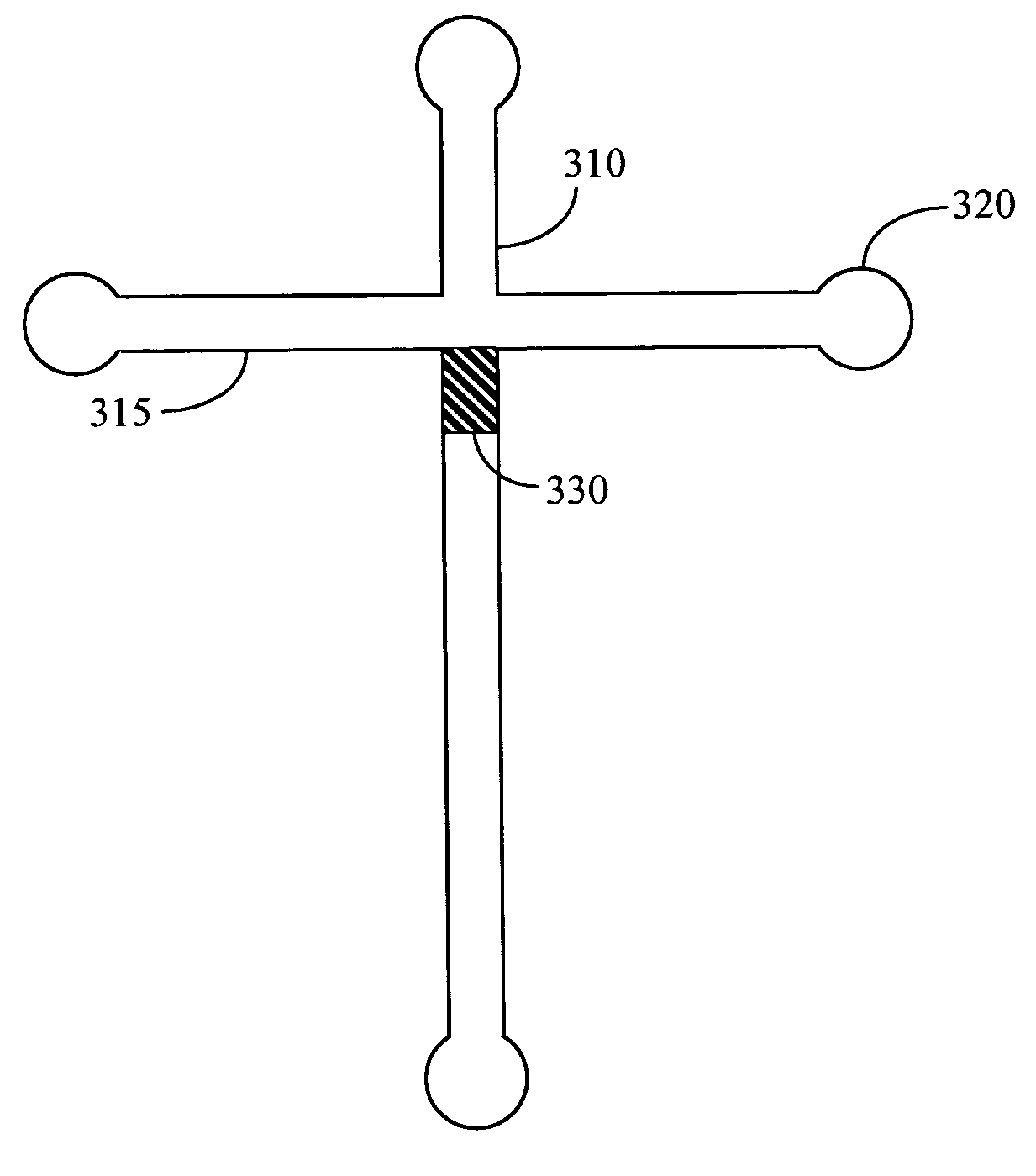
[0022]The present invention provides improved performance in microfluidic devices by significantly reducing or substantially eliminating sample dispersion effects and cross-contamination between channels. A region of reduced cross-section within a microchannel, that can be proximate the channel junctions, is employed to control the electric-field and pressure-driven fluid flows responsible for degraded performance.

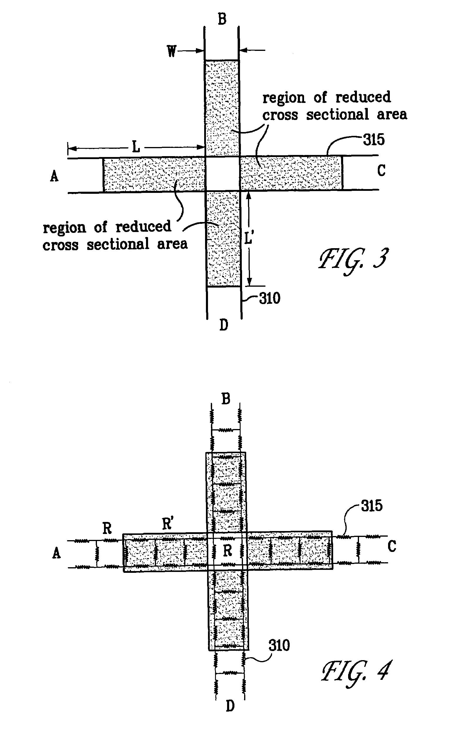
[0023]For the purpose illustrating and exemplifying the present invention, consider a standard geometry presently used in the art, as shown in FIG. 3: two microchannels 310 and 315, having widths W and depths D, that intersect at a junction in a right cross. The widths and depths of the microchannels are typically in the range of 0.1 micron to 1 millimeter. The invention is not limited to this geometry and can apply equally to any number of microchannels of any widths and depths or any arbitrary cross-section, either straight or curved, at intersections of any arbitrary an...


PUM

PropertyMeasurementUnit
sizesaaaaaaaaaa
depthsaaaaaaaaaa
included angleaaaaaaaaaa

Abstract

A method for controlling fluid flow at junctions in microchannel systems. Control of fluid flow is accomplished generally by providing increased resistance to electric-field and pressure-driven flow in the form of regions of reduced effective cross-sectional area within the microchannels and proximate a channel junction. By controlling these flows in the region of a microchannel junction it is possible to eliminate sample dispersion and cross contamination and inject well-defined volumes of fluid from one channel to another.

Description

STATEMENT OF GOVERNMENT INTEREST[0001]This invention was made with Government support under contract no. DE-AC04-94AL85000 awarded by the U.S. Department of Energy to Sandia Corporation. The Government has certain rights in the invention.CROSS-REFERENCE TO RELATED APPLICATIONS[0002]Not applicable.BACKGROUND OF THE INVENTION[0003]This invention pertains to a method for injecting well-defined volumes of fluid from one channel into another at their junction in microscale devices to control cross contamination of the channels of microfluidic devices. Fluid control is accomplished generally by providing increased resistance to electric-field and pressure-driven flow in the form of a region of reduced effective cross-sectional area within the microchannels. The invention further relates to microscale devices employing these methods.[0004]Microchannel devices are finding increasing application for separation, identification, and synthesis of a wide range of chemical and biological material...

Claims


Application Information

Patent Timeline
Patent Type & Authority Patents(United States)
IPC IPC(8): B01L3/02G01N27/447G01N27/453
CPCB01L3/502746B01L2200/0605B01L2300/0861B01L2400/086B01L2400/0421B01L2400/0487B01L2400/0418
Inventor HASSELBRINK, JR., ERNEST F.REHM, JASON E.PAUL, PHILLIP H.ARNOLD, DON W.
Owner NAT TECH & ENG SOLUTIONS OF SANDIA LLC
Why Eureka
Try Eureka