Method of producing a sheet having lenticular lens in pre-selected areas

Inactive Publication Date: 2006-02-07
CONLEY KENNETH E +3
View PDF8 Cites 39 Cited by
  • Summary
  • Abstract
  • Description
  • Claims
  • Application Information

AI Technical Summary

Benefits of technology

[0015]To facilitate higher clarity in viewing desired visual effects, the method of the present invention also provides a high clarity lens which has a first predetermined radius on either side of its distal end with the tip of the lens having a second, larger, predetermined radius. The lens is repeated in pattern forming a plurality of lenticular arrays which are formed on a transparent sheet in pre-selected areas using the method of the present invention. The first predetermined radius on either side of the lens has a certain focal point which dictates the thickness of the overall lenticular sheet. A portion of an image affixed under the center of the second, larger, predetermined radius can be seen without distortion from the side of the lenses as it is out of the focal range of the side portion of the lens. The high clarity lens produced by the method of the present invention provides functions for 3-dimensional visual effects, animation, morph animation characteristics and flip images. The lens produced by the present invention provides an improved sharpness, color intensity and accurateness of the printed image.
[0016]The method of the present invention also provides a high clarity lens wherein the center part or lane under each lens of a pre-selected area may be dropped or eliminated thereby providing a “see through” effect to a second distant object or to another print / image beyond or behind the first print on the backside of the lenticular sheet. The remainder of the area under the lenticular array can contain the full image with no “see through” effect. A flat window pane at the angle of intended distant viewing does not prevent the viewer's attention from being drawn to the print under and at the focal point of the lens segments. This distraction is prevented by putting a lens with a relatively long focal point at the angle where distant viewing would be expected while having adjacent lens segments with a short focal point for viewing at other angles.
[0021]As a result of the method of the present invention in the disclosed embodiments, the center part of the lens is capable of being left blank on the flat side when printing: for example, if printing a three image flip, the center image can be left out or not printed leaving a clear portion of the lens so that the printed sheet can be placed over or adhered to a previously printed image for see through to the previous printed image. This is particularly advantageous for example, when placing the sheet over a movie poster, with the verbiage of coming soon or now showing appearing at an angle by the viewer and the poster from a straight on position. The lenticular sheet produced by the present invention could also have verbiage of some type appearing at an angle taped to an image. This can also be part of a package where the contents are seen clearly inside at a center position. This is also advantageous when putting an image or message on a glass door and you should be able to see what is also on the other side.

Problems solved by technology

A flat window pane at the angle of intended distant viewing does not prevent the viewer's attention from being drawn to the print under and at the focal point of the lens segments.

Method used


Image

  • Method of producing a sheet having lenticular lens in pre-selected areas
  • Method of producing a sheet having lenticular lens in pre-selected areas
  • Method of producing a sheet having lenticular lens in pre-selected areas

Examples


Embodiment Construction

[0040]The present invention will now be described more fully hereinafter with reference to the accompanying drawings in which exemplary embodiments of the invention are shown. However, this invention may be embodied in many different forms and should not be construed as limited to the embodiments set forth herein. These exemplary embodiments are provided so that this disclosure will be both thorough and complete, and will fully convey the scope of the invention to those skilled in the art. Like reference numbers refer to like elements throughout the various drawings.

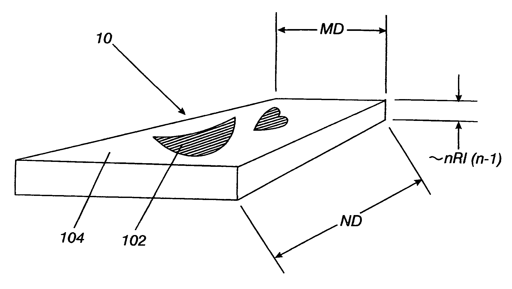
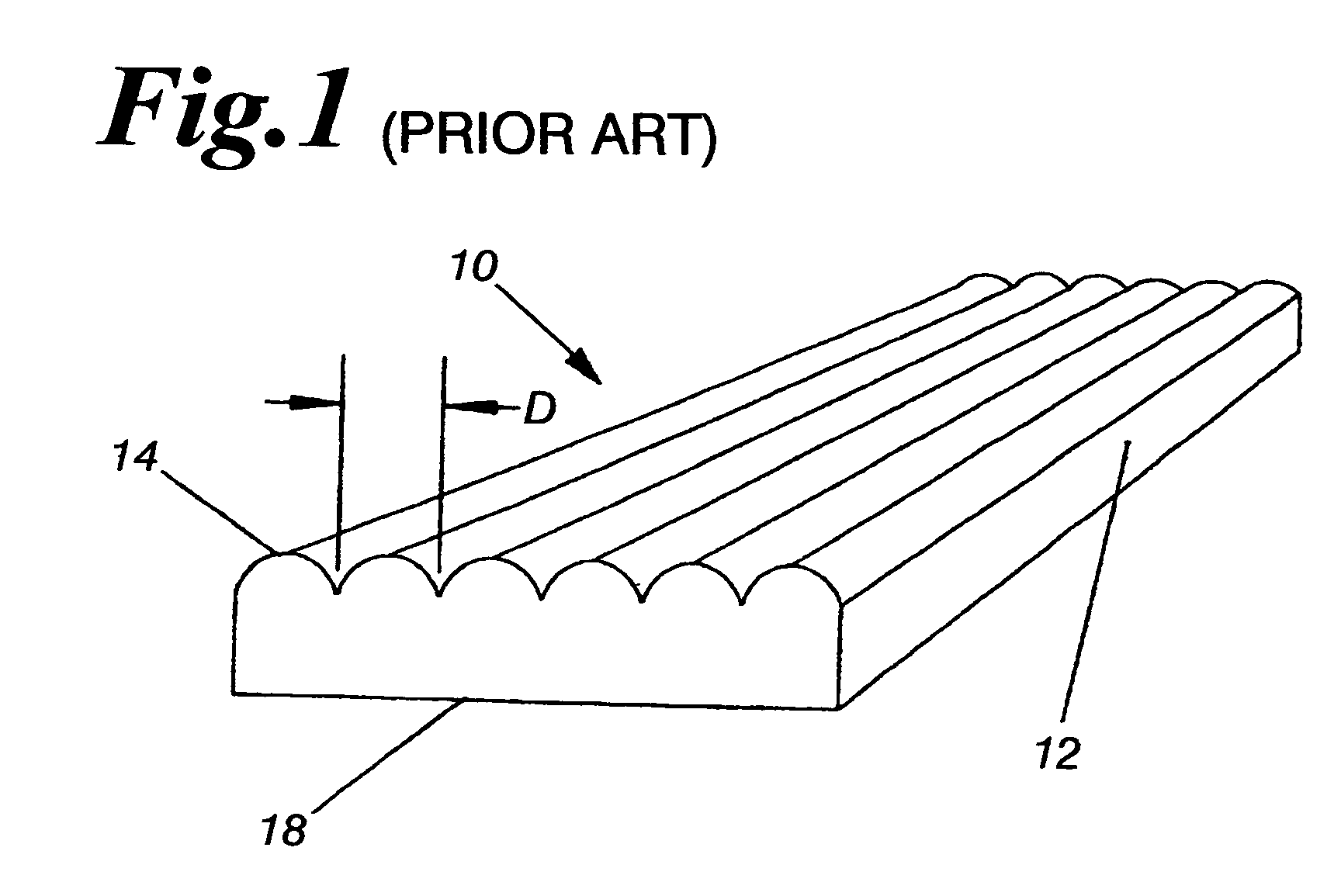
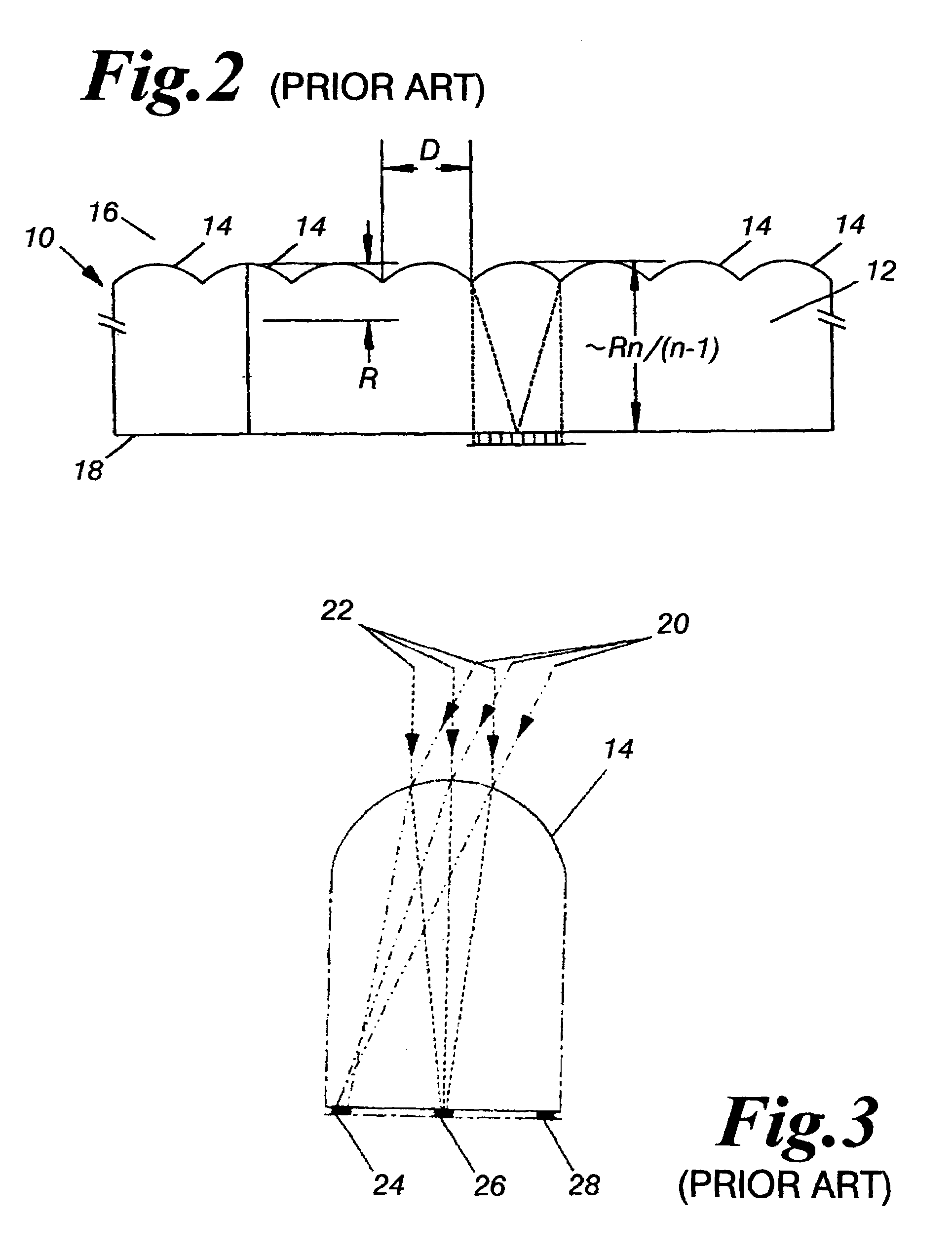
[0041]The present invention provides various embodiments of a method for producing an optical lenticular sheet having high clarity lens arrays located in pre-selected areas. The various embodiments of the present invention may be applied in any known lenticular manufacturing system. As is well known and understood in the art, lenticular lens material utilizes rows of simple and commonly dome-shaped lenses or “lenticules”...


PUM


Abstract

A method of producing a lenticular sheet having anisotropic optical properties comprising the steps of providing a body of transparent material having a pair of opposing sides and an index of refraction greater than one; forming a plurality of lenses on the first side of said pair of opposing sides in pre-selected portions of the first side; and wherein the remainder of the first side of said pair of opposing sides outside the pre-selected lens portions is generally flat and transparent. A method of manufacturing a lenticular sheet comprising the steps of producing a transparent sheet by engraving a desired lens pattern over an entire cylinder or flat plate; placing a mask over selected lens areas; metal plating the unmasked areas to a thickness greater than the surface of the masked areas; and cutting the plated areas back to the level of the masked areas.

Description

CROSS REFERENCE TO RELATED APPLICATION[0001]This application claims the benefit of U.S. Provisional Patent Application Ser. No. 60 / 449,272, filed on Feb. 21, 2003, and is hereby incorporated by reference.BACKGROUND OF THE INVENTION[0002]1. Field of the Invention[0003]The present invention generally relates to a manufacturing method for lenticular sheet products, and more particularly, the present invention relates to a manufacturing method for producing flexible, optical lenticular sheets having high clarity lens arrays located thereon in pre-selected areas operable for use with consumer products.[0004]2. Description of the Related Art[0005]In the commercial industry, it is often desirable to impart visual effects such as three dimensionality or motion characteristics upon packages or labels of consumable products and the like. Due to expense and ease of design, regular print advertising was the pre-eminent and preferred form used on consumables. Regular print advertising is accompl...

Claims


Application Information

Patent Timeline
Patent Type & Authority Patents(United States)
IPC IPC(8): G02B27/10G02B30/27
CPCB29D11/00278G02B3/0031G02B27/2214G02B3/005Y10S359/90G02B30/27
Inventor CONLEY, KENNETH E.CONLEY, MARY E.SMITH, JR., MAX B.DELLINGER, KERRY DWAYNE
Owner CONLEY KENNETH E
Why Eureka
Try Eureka