Fire protection for electronics equipment

a technology for electronics equipment and fire protection, applied in the field of fire protection, can solve the problems of high-power electronic equipment, especially over 200 w, being susceptible to fire damage, and consuming a lot of expensive equipment,

Inactive Publication Date: 2006-02-07
NETWORK APPLIANCE INC
View PDF13 Cites 16 Cited by
  • Summary
  • Abstract
  • Description
  • Claims
  • Application Information

AI Technical Summary

Benefits of technology

[0005]In a first aspect of the present invention, an apparatus for preventing fires in electronic equipment includes a radiation-collecting element for collecting infrared radiation generated within an enclosure of the electronic equipment. A sensor array is coupled to the radiation-collecting element for detecting intensity of the infrared radiation within the enclosure. The sensor array is formed of a plurality of pixels. Each of the pixels provides an electrical value (i.e., a voltage or a current) that is commensurate with the intensity of the infrared radiation received by the pixel. A signal processor detects changes in the intensity of the infrared radiation received by each pixel. A controller interprets the changes in the intensity of the infrared radiation received by each of the plurali

Problems solved by technology

Presently, high power electronic equipment, especially over 200 W, is susceptible to fire damage caused by electrical shorts.
Shorts occur across low voltage power planes and ground on the printed circuit cards within the com

Method used


Image

  • Fire protection for electronics equipment
  • Fire protection for electronics equipment
  • Fire protection for electronics equipment

Examples


Embodiment Construction

[0017]Reference will now be made in detail to the presently preferred embodiments of the invention, examples of which are illustrated in the accompanying drawings.

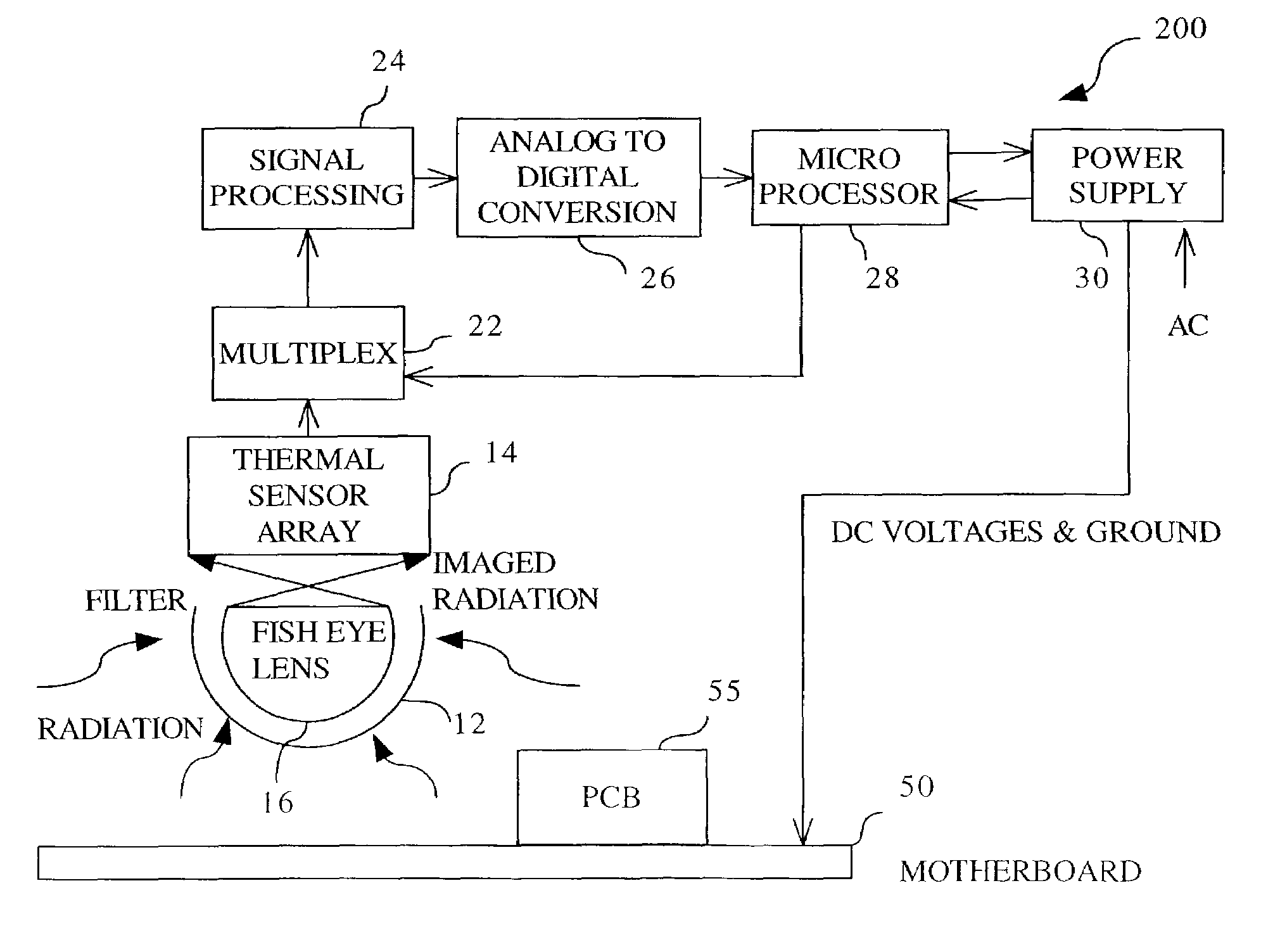
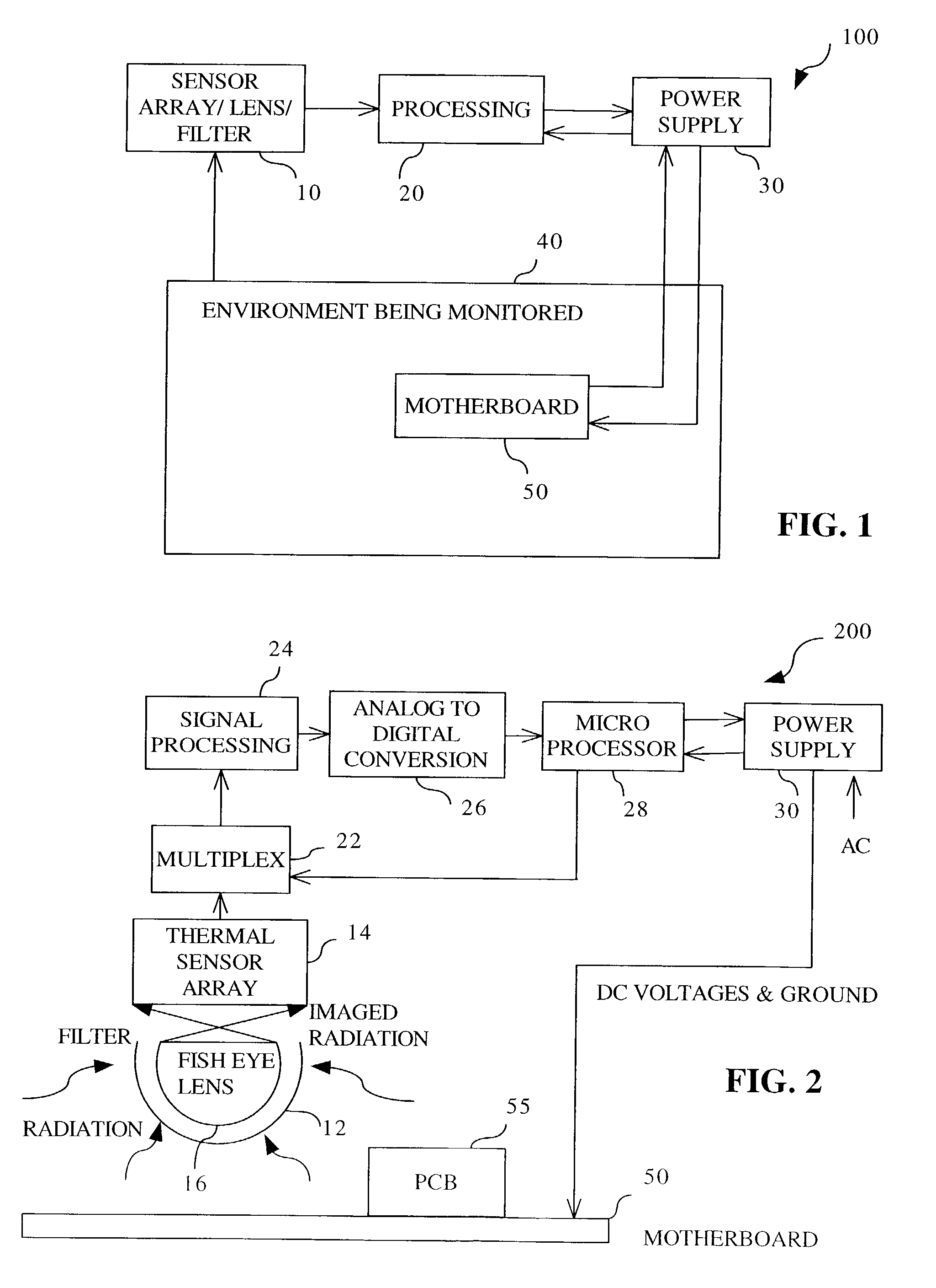
[0018]FIG. 1 illustrates a preferred embodiment 100 of the present invention. A volume 40, preferably an enclosed volume, is continually being measured by a radiation collecting system 10 for potentially detrimental changes in the physical environment. This enclosed volume may contain a heat-producing object, such as a shelf within an electronic equipment cabinet or rack, a motherboard, a printed circuit board, a collection of electronic boards, or the entire cabinet or rack. Examples of electronic equipment contained within the electronic equipment cabinet include servers, routers, hubs, network switches, mainframe electronics, radio frequency measurement equipment, storage devices, medical equipment, power supplies, and the like. The illustration of FIG. 1 depicts the heat-producing object in volume 40 as a motherboard 5...


PUM


Abstract

A method and apparatus for fire prevention in electronic equipment utilizes infrared imaging technology to monitor a substantial region of an enclosure within the electronic equipment. For example, a shelf within a computer cabinet may have a lens and thermal sensor array placed within to detect changes in temperature. A processor interprets the data from the thermal sensor array to determine whether to send an alert to an operator and/or to shut down a power supply.

Description

FIELD OF THE INVENTION[0001]The present invention generally relates to the field of safeguarding electronic equipment, and particularly to a method and apparatus for identifying thermal hot spots within an electronic equipment enclosure and taking corrective action.BACKGROUND OF THE INVENTION[0002]Presently, high power electronic equipment, especially over 200 W, is susceptible to fire damage caused by electrical shorts. Shorts occur across low voltage power planes and ground on the printed circuit cards within the computer cabinet and cause high currents to ignite the printed circuit boards. It has been observed that the electrical short circuits start as a localized hot spot before burning. Because the localized burning is not self-extinguishing, a fire may cause extensive damage to expensive equipment accompanied by a lengthy down time.[0003]Therefore, it would be desirable to provide a system and a method for identifying hot spots within electronic equipment.SUMMARY OF THE INVEN...

Claims


Application Information

Patent Timeline
IPC IPC(8): H02H5/04G08B17/12
CPCG08B17/12
Inventor ZANSKY, ZOLTANTUPY, JOSEPH
Owner NETWORK APPLIANCE INC
Why Eureka
Try Eureka