Optical path for a thermal-assisted magnetic recording head

Inactive Publication Date: 2006-02-07
ADVANCED RES
View PDF59 Cites 23 Cited by
  • Summary
  • Abstract
  • Description
  • Claims
  • Application Information

AI Technical Summary

Benefits of technology

[0010]The present invention, in one embodiment, is a magnetic recording head for writing data onto a magnetic recording medium. The head includes a first pole and a second pole separated by a gap. A coil structure traverses through the gap, and a waveguide exten

Problems solved by technology

The signal-to-noise ratio is a function of the number of grains per bit cell, so as this density i

Method used


Image

  • Optical path for a thermal-assisted magnetic recording head
  • Optical path for a thermal-assisted magnetic recording head
  • Optical path for a thermal-assisted magnetic recording head

Examples


Embodiment Construction

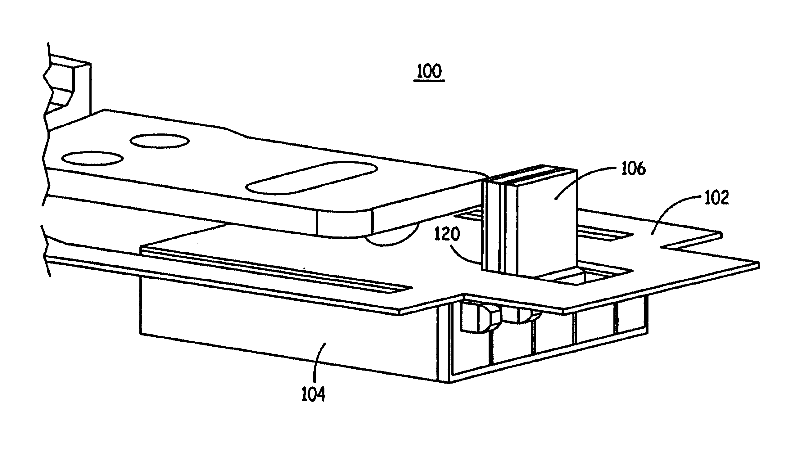
[0024]FIGS. 3A and 3B show a perspective view and a sectional perspective view of a portion of the transducing head 30, according to one embodiment of the present invention. The transducing head 30 is formed near the lower edge of the trailing face of the slider 20. As shown in FIGS. 3A and 3B, the transducing head 30 includes a first pole 32, a second pole 34, and a read / write coil 36. An optical path or waveguide 38 extends from at or near the top face of the slider 20 to near the write gap 40. As shown, the waveguide 38, in this embodiment, extends along a front face of the first pole 32. The read / write coil 36 extends along a front face of the first pole 150 and behind the second pole 152. The read / write coil 36 travels between the waveguide 38 and the second pole 34. The read / write coil 36 is insulated from the poles 32, 34 by an insulating layer.

[0025]As further shown in FIG. 3A, the second pole 34 includes a twin or split back gap through which the waveguide 38 travels. This ...


PUM


Abstract

An optical path or waveguide for a laser-assisted transducing head is disclosed. The optical path extends between the poles of the transducing head to near the write gap. A solid-state laser is attached to or incorporated into the slider or head and is positioned to direct thermal energy through a waveguide and onto a track of a read/write surface to lower the coercivity of the recording medium to facilitate the write process.

Description

CROSS-REFERENCE TO RELATED APPLICATIONS[0001]This application claims priority to U.S. provisional patent application No. 60 / 389,802, entitled “Laser Attached Slider,” filed Jun. 19, 2002, and U.S. provisional patent application No. 60 / 413,190, entitled “Laser Attached Slider,” filed Sep. 24, 2002, both of which are hereby incorporated by reference in their entirety.FIELD OF THE INVENTION[0002]This invention relates generally to magnetic recording heads, including a read element and a write element, for use in a data storage system such as a disk drive. More specifically, it relates to a path for an optical waveguide to carry thermal energy (e.g., light) to a location near the write portion of the magnetic recording head, to enable thermally-assisted writing.BACKGROUND OF THE INVENTION[0003]Typical disk drive systems include suspensions for supporting a transducing head over information tracks of a rotatable disk. Typically, suspensions include a load beam or suspension having a moun...

Claims


Application Information

Patent Timeline
IPC IPC(8): G11B11/00G11B5/00G11B5/127G11B5/31G11B5/48G11B5/58
CPCG11B5/127G11B5/3103G11B5/3116G11B5/313G11B5/48G11B2005/0021G11B5/4886G11B5/58G11B2005/0002G11B2005/0005G11B5/4806
Inventor DUGAS, MATTHEW P.WALLHOFF, JEFFREY A.
Owner ADVANCED RES
Why Eureka
Try Eureka