Apparatus and method for OFDM data communications

a technology of data communication and apparatus, applied in the field of radio data communication, can solve the problems of increasing interference, limited power (or link gain) of sector omni-directional broadcast, and increasing the cost of power to transmit the rf channel to the target mobile terminal(s) with sector omni-directional broadcast,

Inactive Publication Date: 2006-02-07
MALIKIE INNOVATIONS LTD
View PDF18 Cites 95 Cited by
  • Summary
  • Abstract
  • Description
  • Claims
  • Application Information

AI Technical Summary

Benefits of technology

[0007]The present invention is directed to apparatus and method for OFDM data communications. In the present invention, a BTS utilizes a directional beam to transmit data traffic channels to target mobile terminal(s). In one embodiment, the directional beam contains the entire RF channel and rotates through the coverage area such that each mobile terminal within the coverage area can have access to the pilot and signalling channels while the target mobile terminal(s) can have access to the entire RF channel. In other embodiments of the present invention, the RF channel is divided into at least two beams, at least one beam trans

Problems solved by technology

One problem with this implementation is the limited power (or link gain) that a sector omni-directional broadcast is capable of while reaching all of the mobile terminals within the coverage area simultaneously.
At the high bit rates that the data traffic is typically transmitted at, the power to transmit the RF channel to th

Method used


Image

  • Apparatus and method for OFDM data communications
  • Apparatus and method for OFDM data communications
  • Apparatus and method for OFDM data communications

Examples


first embodiment

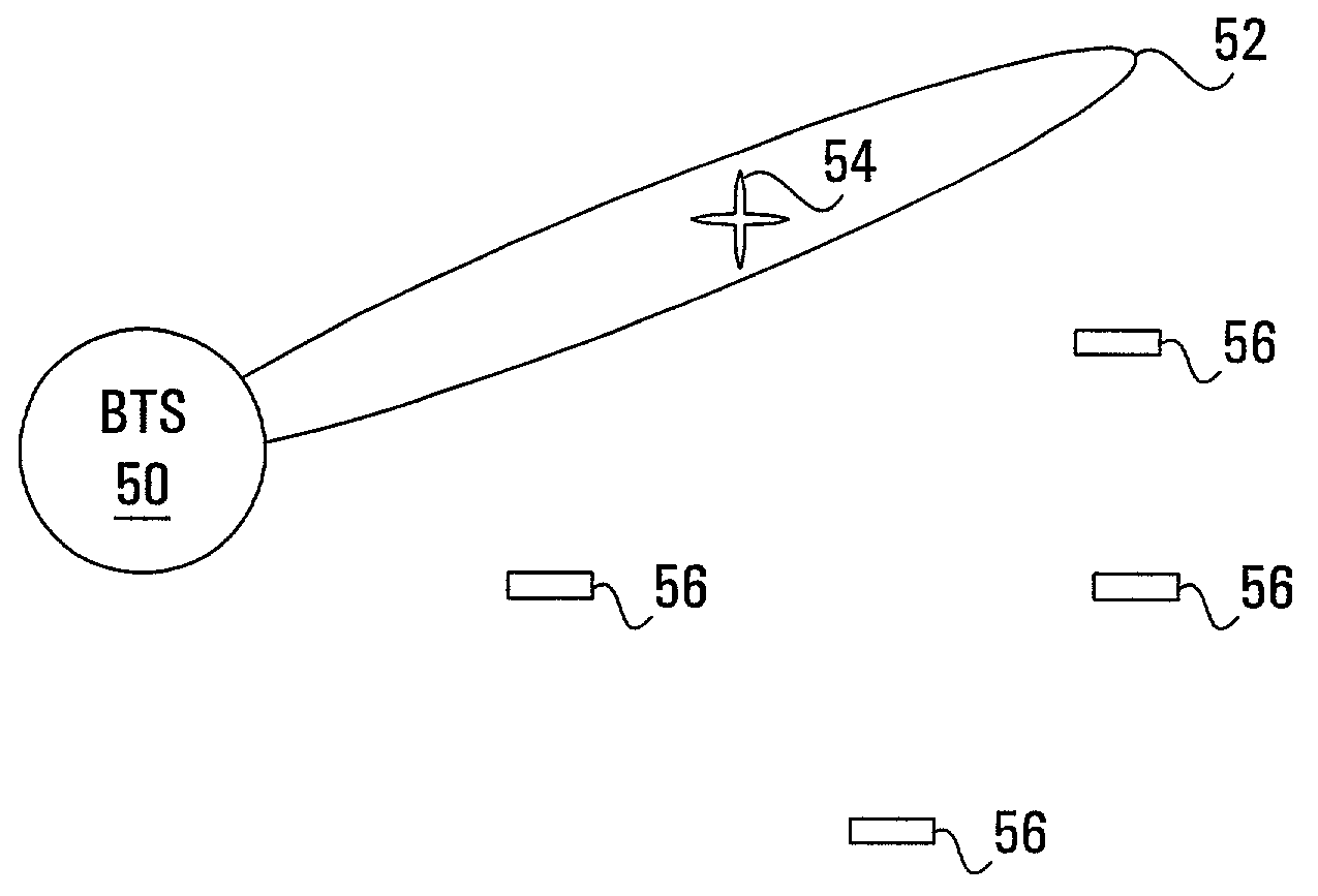
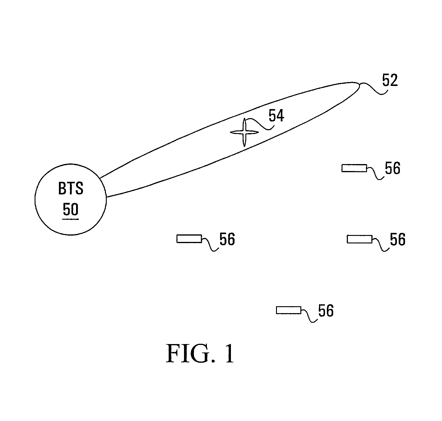
[0033]In the present invention, as illustrated in FIG. 1, a BTS 50 utilizes a directional wireless beam 52 to transmit data traffic channels to a target mobile terminal 54. Data traffic information (within the data traffic channels), as stated above, may include pilot signal information which may be used for channel estimation. The use of a directional beam system allows sufficient link gain to transmit the data traffic channels within the RF channel to the target mobile terminal 54 by steering energy towards the terminal 54 and thus, improving radio link performance. The use of this directional wireless beam achieves the needed power gain to the target mobile terminal 54 as well as reducing interference due to reuse of the same RF channel in neighbouring cells (or even within the same cell). Directing the energy in this way results in other mobile terminals 56 outside of the beam 52 to receive no or very limited amounts of the transmitted signals within the RF channel. Thus, the mo...

second embodiment

[0053]FIG. 5 is a block diagram illustrating a radio system using OFDM, according to the present invention, similar to that depicted in FIG. 1 but with the BTS 50 having a directional transmission beam for the data channels, hereinafter referred to as a data traffic directional beam, and a separate sector omni-directional transmission beam for the pilot and signalling channels, hereinafter referred to as a service sector omni-directional beam. Within FIG. 5, a directional beam 88 is utilized as the data traffic beam in order for the BTS 50 to transmit the data traffic with sufficient link gain to the target mobile terminal 54 while a sector omni-directional beam 89 is utilized as the service beam in order for the BTS 50 to transmit the pilot and signalling channels continually to all of the mobile terminals in its coverage area. A sector omni-directional beam is generally sufficient for transmission of the pilot and signalling channels to the mobile terminals since the bit rate of t...

third embodiment

[0067]FIG. 7 is a block diagram illustrating a radio system using OFDM, according to the present invention, similar to that depicted in FIG. 5 but with the BTS 50 having a data traffic directional beam 118 and a separate service directional beam 119. Within FIG. 7, the data traffic directional beam 118 allows the BTS 50 to transmit the data traffic with sufficient link gain to the target mobile terminal 54 similar to that described for FIG. 6A while the service directional beam 119 allows the BTS 50 to transmit the pilot and signalling channels to all of the mobile terminals in its coverage area. This alternative is particularly advantageous in cases where the link gain of a sector omni-directional beam is not sufficient for transmission of the pilot and / or signalling channels to the mobile terminals. The directional service beam can be swept about the coverage area to reach all of the mobile terminals in time. Additionally, a plurality of service beams 118 could be used to reach a ...


PUM


Abstract

A radio system employing Orthogonal Frequency Division Multiplexed (OFDM) includes a Base Transceiver Station (BTS) along with a number of mobile terminals located within a coverage area of the BTS. In this system, a target mobile terminal is provided with a focused transmission beam to receive high data rate traffic information while the remainder of the mobile terminals are provide with pilot and signalling information. To achieve both objectives, a BTS is implemented with a transmission apparatus that generates a directional transmission beam for the data traffic information. In one design, this directional beam transmits the pilot and signalling information along with the data traffic information by rotating the beam within the coverage area. In another design, the BTS has a transmission apparatus that generates more than one transmission beam. In one case, the BTS transmits a directional transmission beam for the data traffic information required by the target mobile terminal and a second broad transmission beam for the pilot and signalling information required by the all of the mobile terminals. In another case, the BTS transmits two directional transmissions beams, one beam for data traffic information and one rotating beam for pilot and signalling information.

Description

CROSS-REFERENCE TO RELATED APPLICATION[0001]This application claims the benefit of U.S. Provisional Application No. 60 / 258,558, filed Dec. 29, 2000.FIELD OF THE INVENTION[0002]This invention relates generally to radio data communications and, in particular, to apparatus and methods for Orthogonal Frequency Division Multiplexed (OFDM) data communications.BACKGROUND OF THE INVENTION[0003]In an OFDM system, a Radio Frequency (RF) channel (or bearer) that is transmitted from a Base Transceiver Station (BTS) to one or more mobile terminals is subdivided into a plurality of data traffic carriers with overlapping spectrum along with various pilot and common signalling carriers that are distributed across the RF channel. The pilot carriers within an RF channel are utilized to broadcast pilot information, which is generally referred to as a pilot channel, from a Base Transceiver Station (BTS) to one or more mobile terminals, this pilot channel being used by the mobile terminals for frequency...

Claims


Application Information

Patent Timeline
IPC IPC(8): H04B1/38H04L27/26H04W16/28
CPCH04L27/2602H04L27/2614H04W16/28H04L27/2626
Inventor TEO, KOON HOOSTEER, DAVID G.WARD, CHRIS
Owner MALIKIE INNOVATIONS LTD
Why Eureka
Try Eureka