Method and system for asynchronously transferring data

a technology of asynchronous data and data transfer, applied in the field of data transfer, can solve the problems of memory overflow, memory underflow, and significant amount of latency in data transfer between such devices

Inactive Publication Date: 2006-02-07
PMC-SIERRA
View PDF21 Cites 20 Cited by
  • Summary
  • Abstract
  • Description
  • Claims
  • Application Information

AI Technical Summary

Problems solved by technology

This unfortunately, under some conditions, can introduce a significant amount of latency in the transfer of data between such devices.
It is known that if the cumulative input of data into the buffer significantly exceeds the cumulative output of data by the buffer, memory overflow can result.
Conversely, if the cumulative output of data from the buffer exceeds the cumulative inflow of data over a significant period of time, memory underflow or the emptying of the buffer memory and the output of invalid data may result.
One drawback of known flag circuitry is that complex comparison circuitry is required.
The comparators themselves require complicated logic.
Synchronization logic that enables comparison ...

Method used


Image

  • Method and system for asynchronously transferring data
  • Method and system for asynchronously transferring data
  • Method and system for asynchronously transferring data

Examples


Embodiment Construction

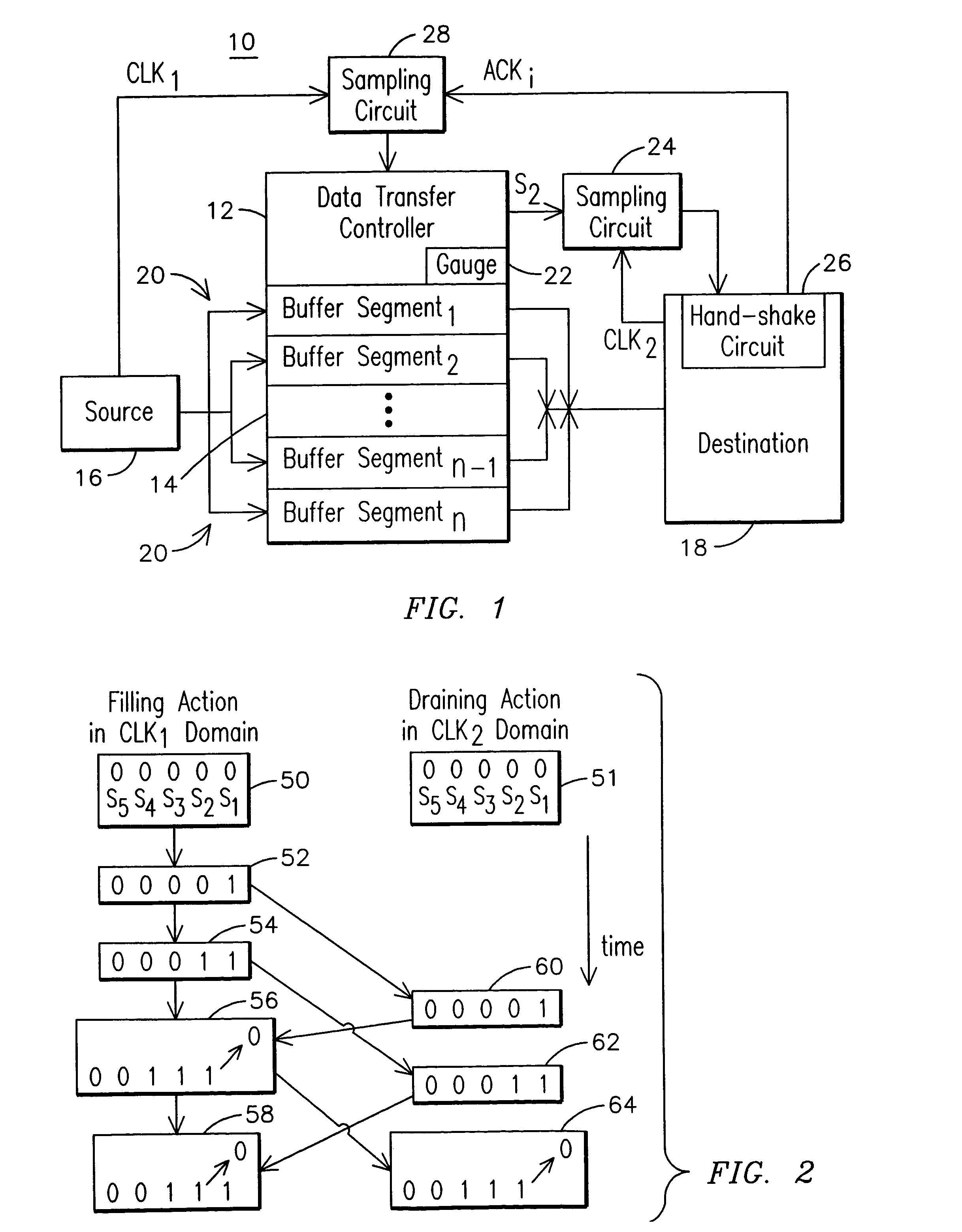
[0017]FIG. 1 illustrates a system 10 including a data transfer controller 12 for asynchronously transferring data by way of a buffer device 14, such as a first-in, first-out, last-in, last-out, or any other type of generally temporary storage device, between a data source device 16 and data destination device 18. A buffer-segment module, conceptually represented by branches 20, is configured to define a plurality of buffer segments in the buffer device, e.g., buffer SEGMENT1 through buffer SEGMENTn. In one exemplary embodiment, the size and / or number of the buffer segments may be dynamically adjustable from a selectable range of buffer segment size and / or number. For example, assuming the total size of the buffer is 512 bytes, and further assuming that the selectable range of the number of segments is from two to eight buffer segments, then the size of each segment would be equal to 64 bytes in case the buffer was mapped or divided into eight buffer segments. Conversely, the size of...


PUM


Abstract

The present invention provides method, data transfer controller and system for asynchronously transferring data. The method allows to provide a buffer device. The method further allows to define in the buffer device a plurality of buffer segments. Respective ones of the buffer segments are filled with data from at least one data source device operating in a respective clock domain. Upon any respective buffer segment being filled up, the method allows to generate an indication of availability of the contents of the respective buffer segment to at least one data destination device operating in a respective clock domain. The clock domain of the at least one source device is distinct than the clock domain of the at least one destination device.

Description

[0001]This application is a continuation of U.S. patent application Ser. No. 09 / 923,558, filed Aug. 7, 2001, now abandoned.[0002]The present invention is generally related to data transfer between devices running at different clock rates, and, more particularly, the present invention is related to a data transfer technique that allows to divide or map a buffer device into a plurality of segments for more efficient and reliable execution of data transfer between such devices.[0003]A buffer or memory unit can be used to temporarily store information for transfer between two devices running at different clock rates. Separate input and output terminals on the buffer allow data to be input into the buffer at one clock rate and output from the buffer at a different clock rate. Thus, when the buffer is placed between a data source device and a data destination device running on two different clock rates, the buffer can match data flow between the two units by accepting data from a source u...

Claims


Application Information

Patent Timeline
IPC IPC(8): G06F3/00
CPCG06F5/14G06F2205/108G06F2205/063
Inventor HILL, TIMOTHY R.TROCINE, THOMAS
Owner PMC-SIERRA
Why Eureka
Try Eureka