
Mobile communication terminal, server, communication system, communication control method, and communication control program

a mobile communication terminal and server technology, applied in the field of mobile communication terminals, can solve the problems of increasing the traffic in cellular communication networks, consuming a huge amount of power for reception transactions at intervals of predetermined time, and affecting the efficiency of mobile communication, so as to reduce the transmission processing load, reduce the network traffic, and smooth the communication traffic

Inactive Publication Date: 2007-10-09
NTT DOCOMO INC
View PDF15 Cites 18 Cited by
  • Summary
  • Abstract
  • Description
  • Claims
  • Application Information

AI Technical Summary

Benefits of technology

The present invention relates to a mobile communication terminal and a communication system that can switch between different modes based on a switching signal. The mobile communication terminal has identification information receiving means for receiving identification information from a mini-communicator, cellular communication means for communicating with a server or another terminal via a cellular network, and switching control means for performing mode switching control based on the received switching signal. The communication system can also include a server for transmitting the switching signal to the mobile communication terminal. The invention allows for appropriate switching among the different modes based on the user's needs and can reduce charges on the users by controlling the modes used by them. The mode switching control can be performed based on the user's request, the network state, and the user's location. The invention also includes means for estimating the location of the mini-communicator and the mobile communication terminal.

Problems solved by technology

This trend leads to generating a lot of preowned cell phones every year, and it can be said that how such a lot of preowned cell phones should be effectively utilized is a significant issue.
Under the circumstances as described above, it is conceivable to provide the cell phones with an RFID information receiving function of receiving signals from RFIDs, and simply providing the cell phones with the RFID information receiving function can cause the problem as described below.
Namely, if the RFID information receiving function is activated before the cell phones are handled as preowned cell phones (during a period in which each cell phone is used as a mobile terminal for cellular communication), reception transactions at intervals of predetermined time will consume a massive amount of power.
On the other hand, if the function as a mobile terminal for cellular communication is activated after the cell phones are handled as preowned cell phones, it will result in increasing the traffic too much in cellular communication networks.

Method used


Image

  • Mobile communication terminal, server, communication system, communication control method, and communication control program
  • Mobile communication terminal, server, communication system, communication control method, and communication control program
  • Mobile communication terminal, server, communication system, communication control method, and communication control program

Examples


first embodiment

Various Modifications about First Embodiment

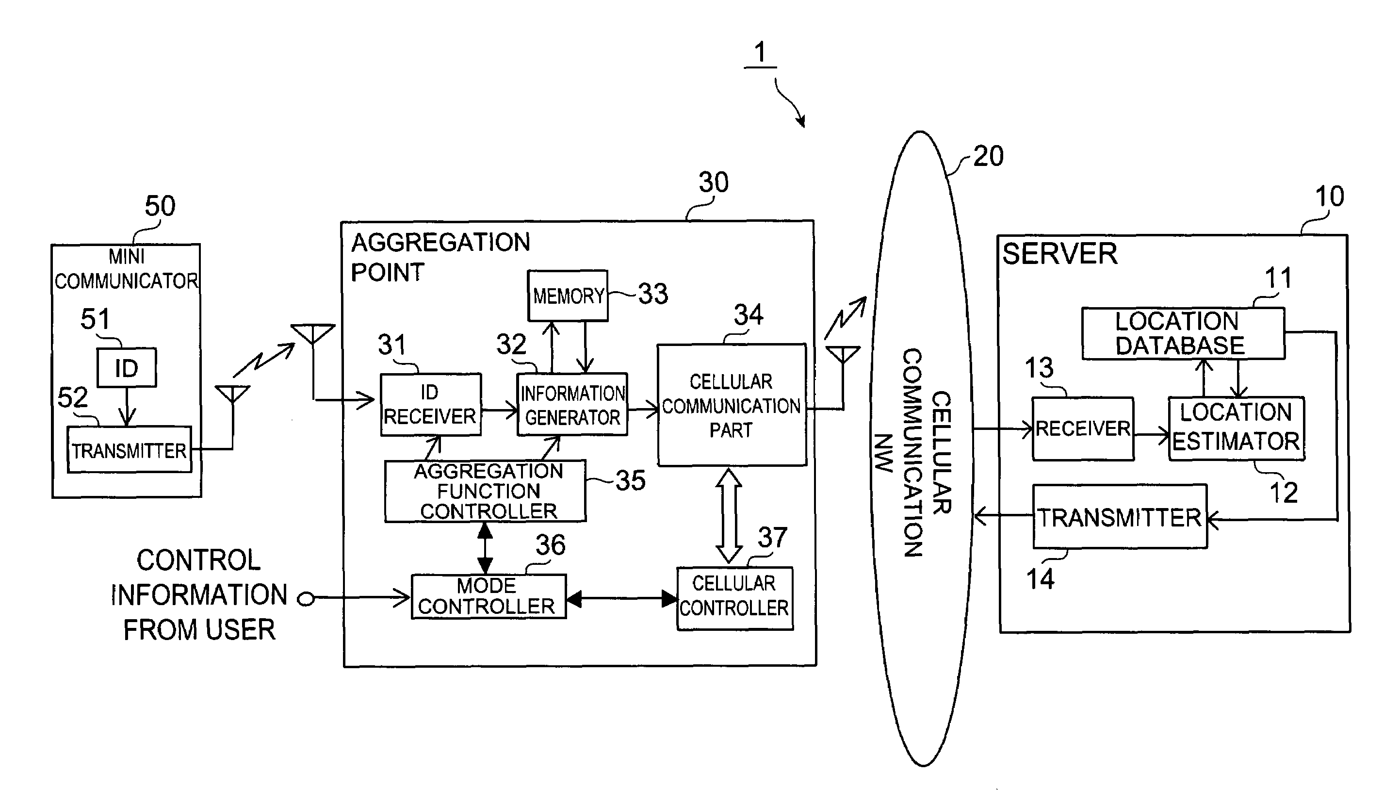
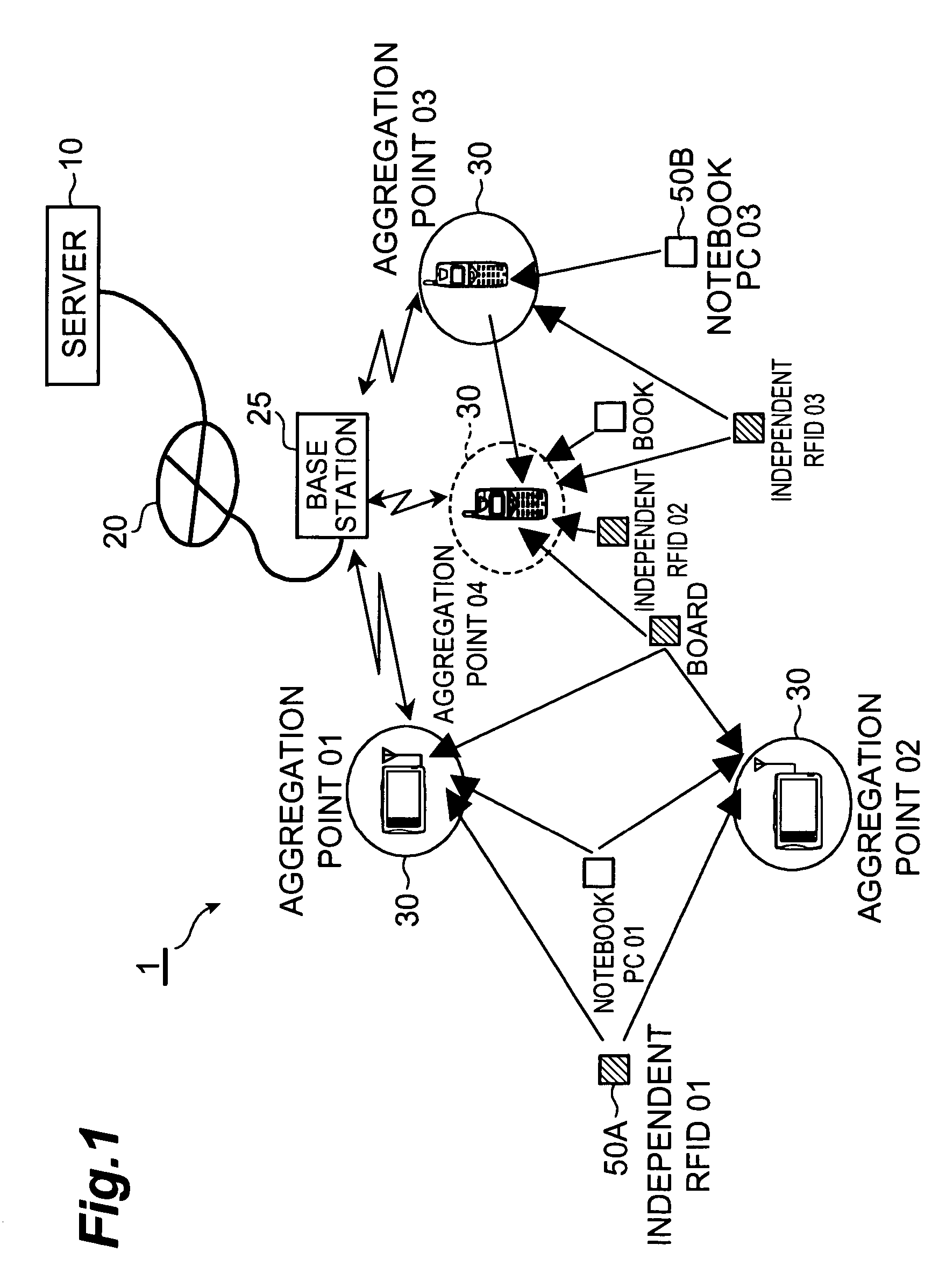
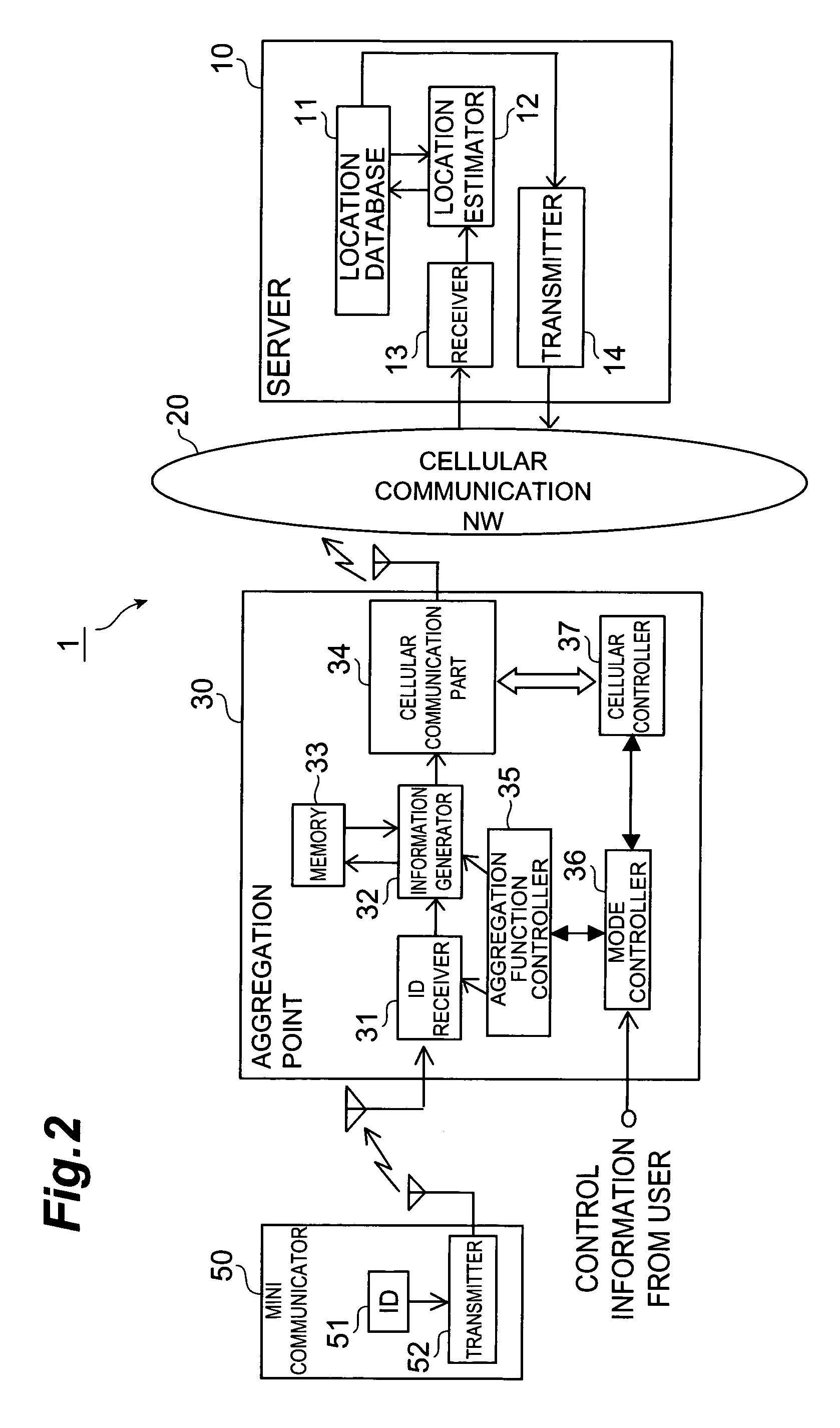
[0110]The component for estimating the location of RFID 50 does not have to be limited to server 10, but may be the aggregation point 30. Namely, the aggregation point 30 is arranged to further receive from another aggregation point, other terminal information containing an ID of an RFID, the reception intensity of the radio wave from the RFID, and the location information of the other aggregation point, whereby the aggregation point 30 can estimate the location of the RFID in similar fashion to above, based on the reception intensity of the radio wave from the RFID measured by itself and on the other terminal information thus received. In this case, the processing load increases on each aggregation point, while there is the advantage that the traffic can be reduced in the cellular communication network. Specifically, as shown in FIG. 28, the aggregation point 30X is preferably configured to further comprise location database 44B memorizin...

second embodiment

[0113]The second embodiment will illustrate a configuration of RFID 50 for preventing interference.

[0114]There are cases in which a plurality of RFIDs 50 simultaneously transmit their radio waves to one aggregation point 30. For this reason, it is necessary to adopt some means for preventing interference among the radio waves from the RFIDs 50 at aggregation point 30. A solution is a method of preliminarily determining transmission intervals of radio waves from RFIDs 50 individually for the respective RFIDs and letting each RFID 50 transmit the radio wave at the transmission intervals determined. In use of this method, even if radio waves from different RFIDs 50 temporally overlap each other at a certain timing to cause interference, the radio waves will not temporally overlap each other at the next transmission timing, so as to prevent interference.

[0115]Other methods include a method of randomly changing the transmission intervals of radio wave from the same RFID 50 by itself, a m...

third embodiment

[0116]Next, the third embodiment will illustrate an embodiment in which the aggregation point 30 authenticates whether an RFID 50 as a transmitter of a radio wave is a qualified one. In the present embodiment, specific configurations are provided in RFID (mini-communicator) 50 as shown in FIG. 11 and in ID receiving part 31 in aggregation point 30 as shown in FIG. 12.

[0117]As shown in FIG. 11, RFID 50 is comprised of time stamp generating part 54 which generates a time stamp indicating a transmission time of ID information; signature generating part 55 which generates an electronic signature; private key storage part 56 which stores a private key; ID memory part 51 comprised of a ROM or the like memorizing the ID information of the RFID; multiplexing part 57 which multiplexes the ID information, time stamp, and electronic signature; and transmission part 52 which transmits the multiplexed information through a radio link.

[0118]As shown in FIG. 12, ID receiving part 31 is comprised o...


PUM


Abstract

An object of the present invention is to enable appropriate switching among a plurality of modes including a cellular communication mode and an RFID information receiving function. A communication system is comprised of an RFID configured to transmit predetermined ID information of its own, a server capable of being connected to a cellular communication network, and an aggregation point for aggregating information from the RFID. In the communication system, the aggregation point, which is comprised of a mobile communication terminal or the like, is provided with an ID receiver for receiving ID information from an RFID, and a cellular communication part for performing cellular communication via the cellular communication network. Furthermore, the aggregation point is provided with a new mode controller for receiving a switching signal for switching among a plurality of modes including the cellular communication mode and the RFID information receiving function from the server, and for performing a mode switching control based on the received switching signal.

Description

BACKGROUND OF THE INVENTION[0001]1. Field of the Invention[0002]The present invention relates to a mobile communication terminal, a server, a communication system, a communication control method, and a communication control program.[0003]2. Related Background Art[0004]The users of cell phones are now no fewer than seventy millions in Japan, and a great number of users tend to buy a new cell phone every few years. This trend leads to generating a lot of preowned cell phones every year, and it can be said that how such a lot of preowned cell phones should be effectively utilized is a significant issue.[0005]On the other hand, inexpensive RFIDs (Radio Frequency Identifications), which transmit information containing their own identification number at regular intervals, are commonly known, and there are also proposals on technologies and others of using such RFIDs to track links among spread goods, delivery vehicles, and warehouses in real time, thereby enabling estimation of delivery t...

Claims


Application Information

Patent Timeline
Patent Type & Authority Patents(United States)
IPC IPC(8): H04Q7/20H04B5/48H04B7/26H04W88/02H04W88/06
CPCH04W88/06H04W88/02H04B7/26
Inventor SUDA, HIROHITOOHKUBO, SHINZOMASAMURA, TATSUROTANAKA, TOSHIAKIMURATA, MITSURU
Owner NTT DOCOMO INC
Learn More