Hardware-operation description conversion method and program therefor

a hardware operation and description technology, applied in the direction of program control, instruments, cad circuit design, etc., can solve the problems of rtl simulation on computer and software simulation that takes a long tim

Inactive Publication Date: 2006-02-07
KK TOSHIBA
View PDF22 Cites 39 Cited by
  • Summary
  • Abstract
  • Description
  • Claims
  • Application Information

AI Technical Summary

Benefits of technology

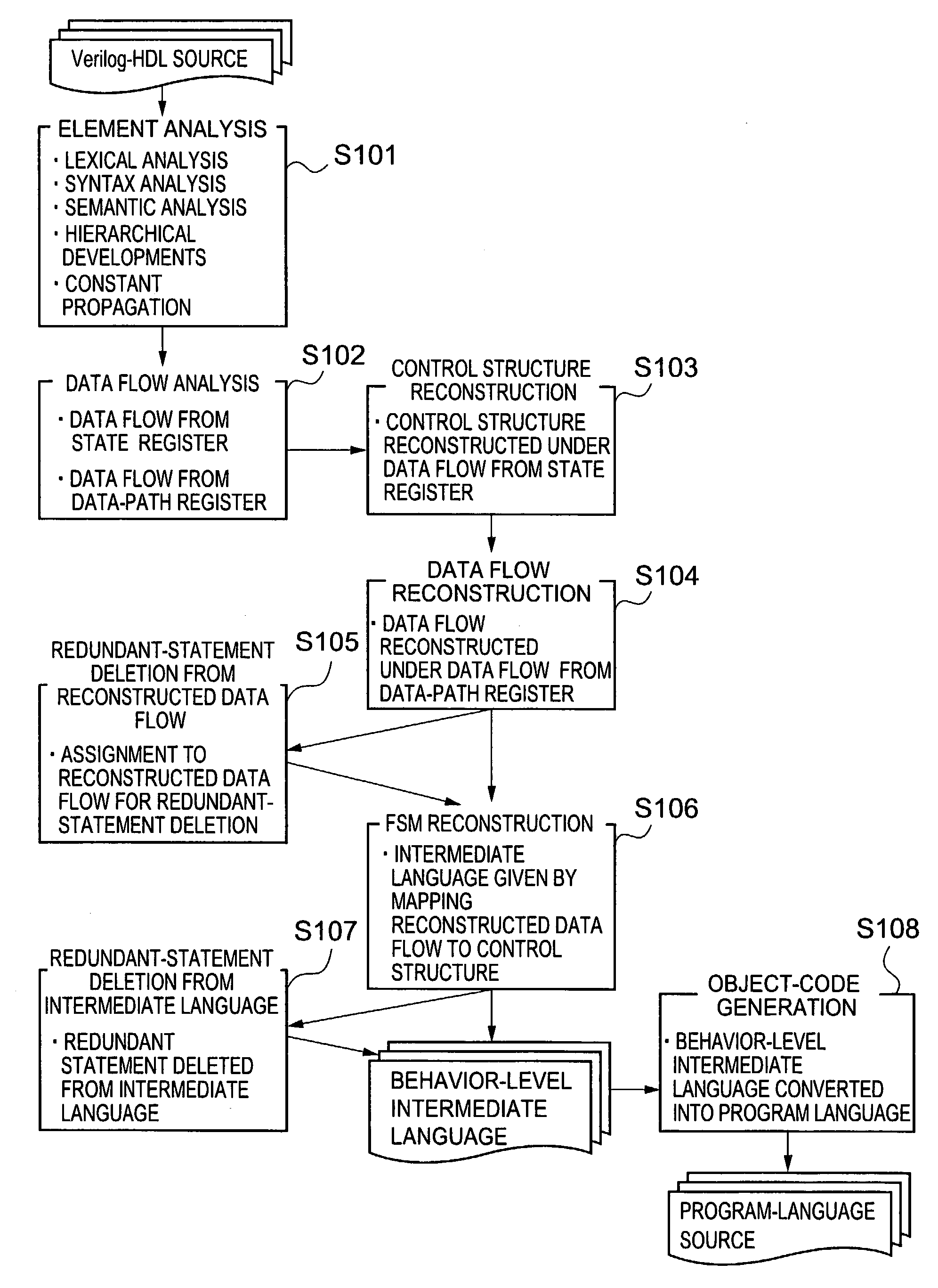
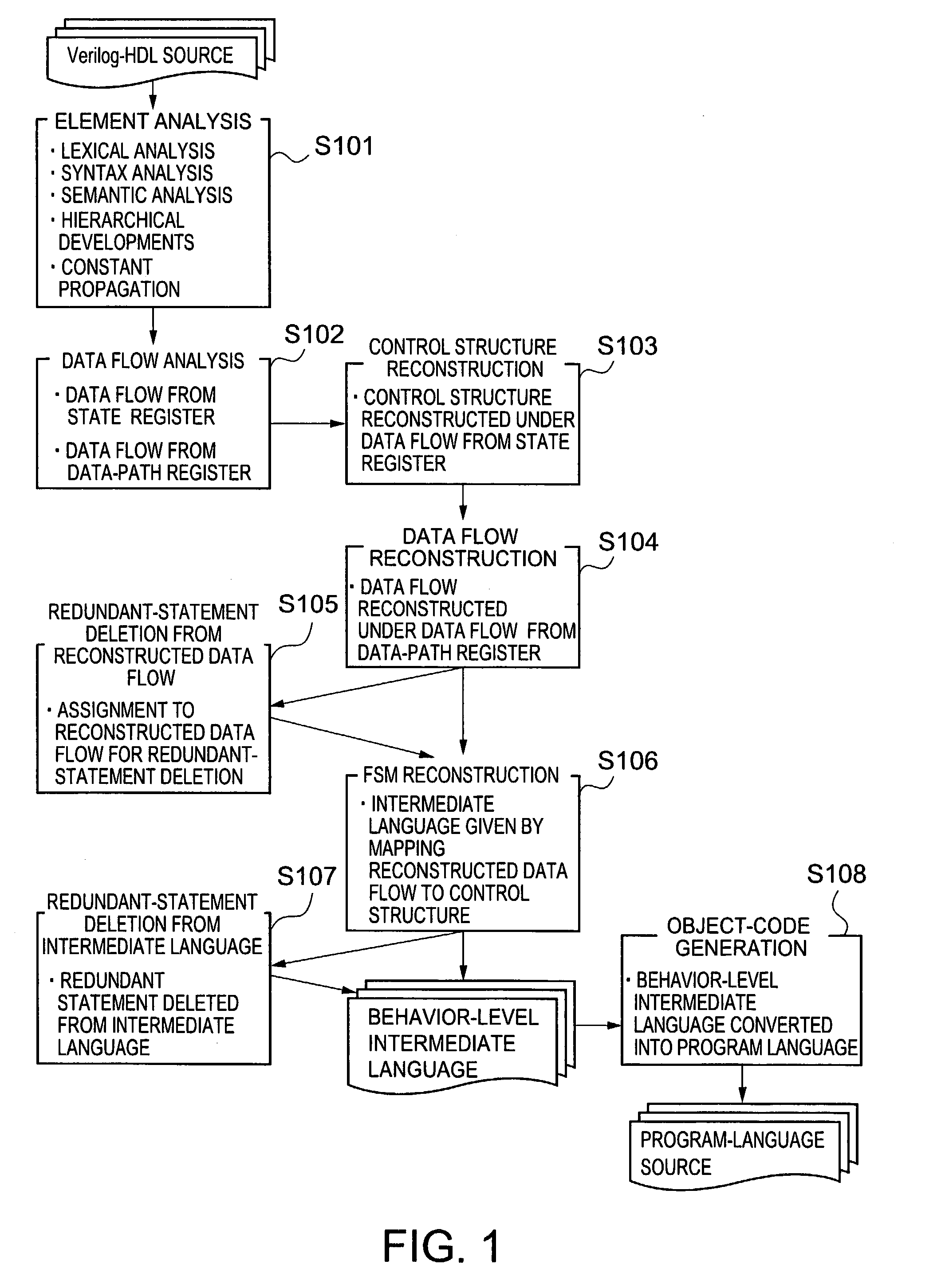
[0024]A first aspect of the present invention is a method of converting RTL description to a computer-executable program language by a computer, the RTL description describing hardware, the hardware including a controller and a data path, the controller having a state register and a first combinational circuitry, the data path having a data-path register controlled by a control signal from the controller and a second combinational circuitry, the computer functioning as an element analyzer, a data-flow analyzer, a control-structure reconstructer, a data-flow reconstructer, a control-structure/data-flow combiner and an object-code generator, the method comprising: analyzing elements of the RTL description, at the element analyzer; creating a first data flow from the state register and a second data flow from the register in the data path, at the data-flow analyzer; reconstructing a control structure in which the controller controls the data path based on the first data flow, at the control-structure reconstructer; reconstructing the second data flow to create a data flow from the data-path register operating in each state of the control structure, at the data-flow reconstructer; mapping each reconstructed data flow in each state of the control structure, thus outputting an behavior-level interme

Problems solved by technology

Simulation of the RTL description by software takes much time because of huge number of actions including the behavior of hardware to be operated.
As discussed, the RTL description is based on “synchronization at clocks”, thus RTL simulation on computer takes much time.
Verilog2C++ sequential processing of the RTL description for the hardware sh

Method used


Image

  • Hardware-operation description conversion method and program therefor
  • Hardware-operation description conversion method and program therefor
  • Hardware-operation description conversion method and program therefor

Examples


example 3

Exemplary Reconstruction of Data-Path Data Flow

[0235]Listed below is a source code 16, an exemplary reconstructed data-path data flow in a state STATE0 of the FSM, the example in the control-structure reconstruction step to the data flow, the example in the data-path-register-originated data-flow creation step.

[0236]The control signal in STATE0 is described as follows. The left-side numerals in the reconstructed data flow are line numbers in the RTL description shown in FIG. 22 to 26.

[0237](Source Code 16)[0238] / / control signal[0239]34: m1c1′b0;[0240]35: m2c1′b0;[0241]36: m3c1′b0;[0242]37: v3c1′b1;[0243]38: v4c1′b1;[0244]39: v6c1′b0;[0245]40: v5c1′b0;[0246]41: a—mux—c1′b1;[0247]42: b—mux—c1′b1;

[0248]The following is the data flow before reconstruction. The left-side numerals in the reconstructed data flow are line numbers in the RTL description shown in FIGS. 22 to 26.

[0249](Source Code 17)[0250] / / data flow[0251]109: b—mux—c—out—mux c;[0252]105: a—mux—c—out—mux—c;[0253]101: v2—out2—...

example 1

Conversion of Concatenation to Language C

[0352]Concatenation statements shown below require that 255 be ANDed with each bit for supplying eight lower-significant bits of a signal “c” to a signal “b”. It is also required that the signal “c” be shifted in right by 8 bits and 255 be ANDed with each bit for supplying eight upper-significant bits of the signal “c” to a signal “a”.

[0353](Source Code 25)[0354]wire [7:0]a, b;[0355]wire [15:0]c;[0356]{a, b}=c;

[0357]The results are equivalent conversion as shown below:

[0358](Source Code 26)[0359]unsigned long a, b, c;[0360]b=c & 255U;[0361]a=(c>>8) & 255U;

example 2

Conversion to Language C

[0362]Listed below is exemplary Language C converted from the intermediate language created in the control-structure / data-flow combination step, with the one-to-one conversion and concatenation discussed above.

[0363]

(Source Code 27)state = next—state;switch (state) {case 0:next—state = 1;add—out = (v2—in+v3—in) & 255UL;—add—tmp = ((v2—in+v3—in) >> 8) & 1UL;mul—out = (v3—in*v4—in) & 255UL;—mul—tmp = ((v3—in*v4—in) >> 8) & 255UL;break;case 1:next—state = 2;v6—out = add—out;—add—tmp = ((add—out+mul—out) >> 8) & 1UL;add—out = (add—out+mul—out) & 255UL;mul—out = (v1—in*v2—in) & 255UL;—mul—tmp = ((v1—in*v2—in) >> 8) & 255UL;break;case 2:next—state = 0;v6—out = add—out;add—out = (v2—in+mul—out) & 255UL;—add—tmp = ((v2—in+mul—out) >> 8) & 1UL;mul—out = (mul—out*v6—out) & 255UL;—mul—tmp = ((mul—out*v6—out) >> 8) & 255UL;break;}

[0364]The resultant source of Language C is listed below, with deletion of redundant statements among new ones created by concatenation.

[0365]

(...


PUM


Abstract

A verilog-HDL source at the register-transfer level (RTL) is converted into a programming language executable on computer. Constructed in an analyzing of elements is a data structure corresponding to the elements of the verilog-HDL source. Created in an analyzing of a data-flow are a first data flow from a state register and a second flow from data-path register. Reconstructed in a reconstructing of a control-structure is the first data flow. Reconstructed in a reconstructing of a data-path is the second data flow so that the reconstructed second data is constituted only by circuitry operating in each state of the control structure. Each reconstructed data flow is mapped in each state of the control structure in a combining of the control-structure/data-flow, to output an behavior-level intermediate language. The intermediate language is converted into a programming language in a generating of an object-code.

Description

CROSS REFERENCE TO RELATED APPLICATIONS[0001]This application is based upon and claims benefit of priority from the prior Japanese Patent Application No. 2002-178945 filed on Jun. 19, 2002 in Japan, the entire contents of which are incorporated by reference.FIELD OF THE INVENTION[0002]The present invention relates to a method of hardware-operation description conversion and a program therefor. More particularly, this invention relates to a method of gaining resultant outputs with no redundant computations in conversion from hardware-operation description called RTL (Register-Transfer-Level) to hardware operations (behavior) and also to computer languages.BACKGROUND OF THE INVENTION[0003]Hardware designs usually employ a description technique called RTL. The RTL description is based on “synchronization at clocks”. Simulation of the RTL description by software takes much time because of huge number of actions including the behavior of hardware to be operated. The RTL-description simul...

Claims


Application Information

Patent Timeline
IPC IPC(8): G06F17/50G06F17/28G06F9/45
CPCG06F17/5022G06F30/33
Inventor AKIBA, TAKASHIIGARASHI, MASATO
Owner KK TOSHIBA
Why Eureka
Try Eureka