
Lubricant cooling system for a motor vehicle axle

Inactive Publication Date: 2006-02-14
DANA AUTOMOTIVE SYST GRP LLC
View PDF18 Cites 98 Cited by
  • Summary
  • Abstract
  • Description
  • Claims
  • Application Information

AI Technical Summary

Benefits of technology

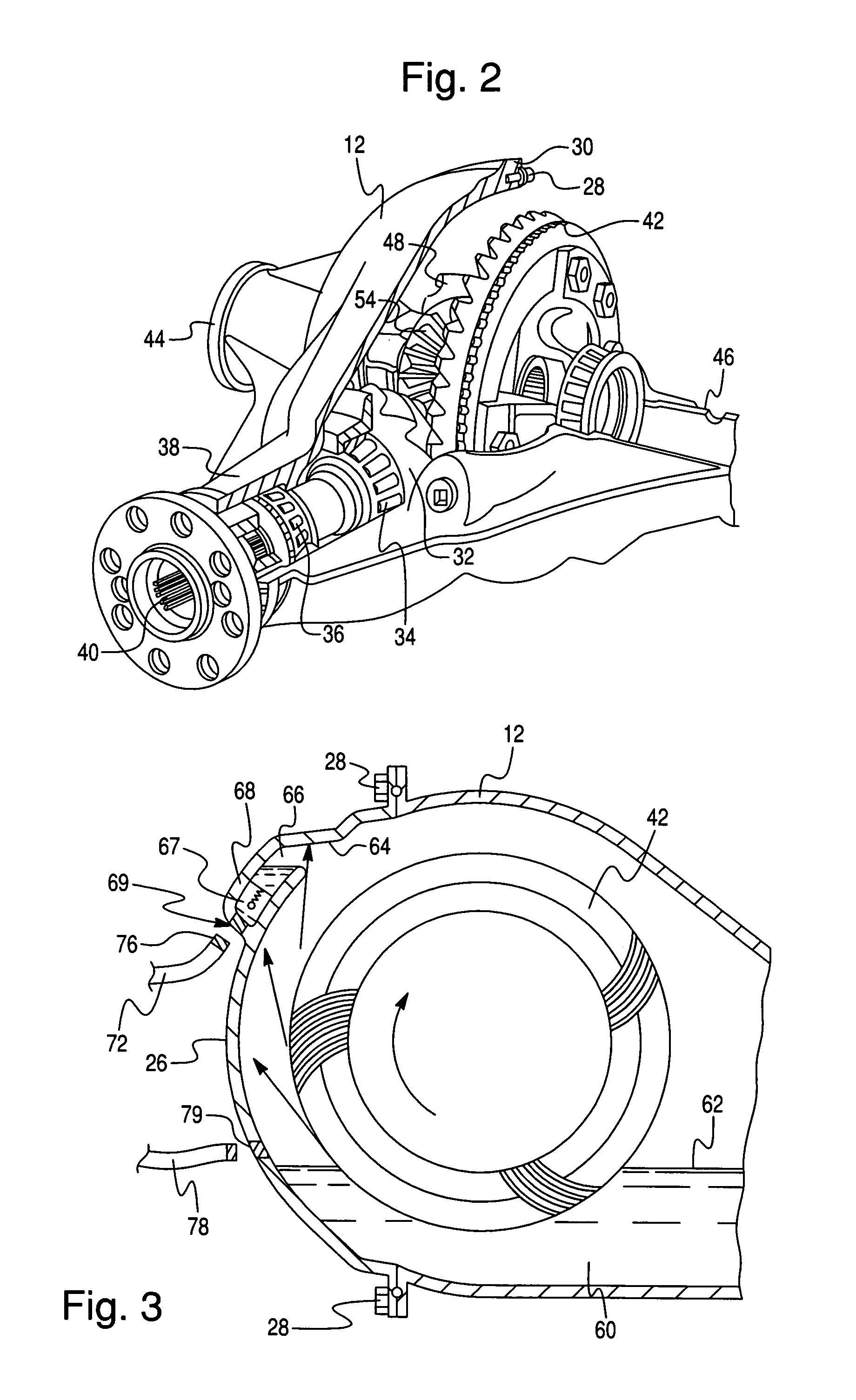
[0010]In the preferred embodiment, the pumping action is accomplished by the cover plate following the contour of the ring gear. Oil is trapped between the contour of the cover plate and forced to travel in the same direction as the ring gear. When the oil being pumped by the ring gear crosses the oil scrapper / pump outlet, the oil flows into a cavity on the cover plate. The oil cavity captures oil, when the oil in this cavity reaches a predetermined temperature (e.g., above 200° F.) a bimetallic spring retracts opening a valve and allowing oil to flow through the cooler system and back into the sump. The purpose of the valve is to prevent cool oil from flowing into the cooler and then turning into a semi-solid in the cooler where the ambient temperature is very cool.
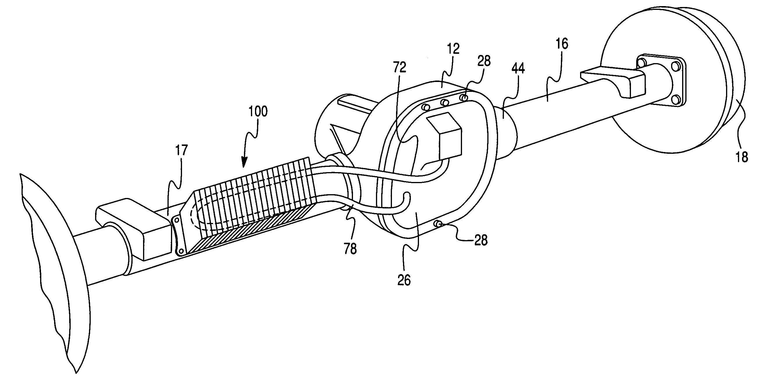
[0012]Several advantages result from the lubricant circulation system according to this invention. It is a low cost, efficient and effective system for cooling axle lubricant. This system requires no additional pumping source or heat exchanger. The system permits a retrofit design formed by the cover plate and frame mount oil cooler.

Problems solved by technology

Axle lubricants are adversely affected by high temperature.
Their performance deteriorates gradually when their temperature is excessive.
Lubricant deterioration and excessive temperatures can cause the bearing, seals, gears and lubricant to fail causing axle failure and increased costs.
A pump and finned heat transfer surfaces add cost to the system, and the pump adds to the power load.

Method used


Image

  • Lubricant cooling system for a motor vehicle axle
  • Lubricant cooling system for a motor vehicle axle
  • Lubricant cooling system for a motor vehicle axle

Examples


Embodiment Construction

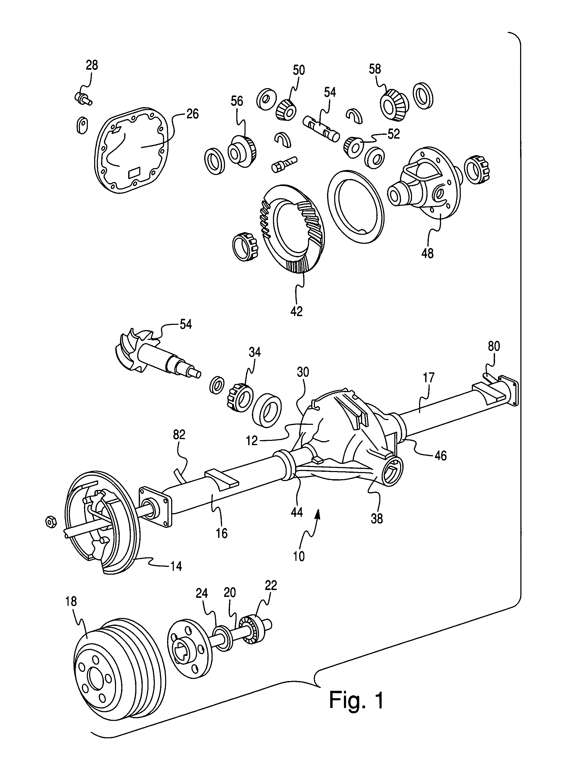
[0017]Referring first to FIG. 1, an axle assembly, to which the present invention can be applied, includes axle housing 12, which contains a differential mechanism and a reservoir of hydraulic lubricant; brake assembly 14 located at the end of a tube 16 extending outboard from the ends of the axle housing 12; brake drum 18; axle shaft assembly 20; axle shaft bearing 22; and bearing seal 24.

[0018]A cover 26 is connected by bolts 28 to the rear face 30 of the housing 12 hydraulically seals the housing against the passage of lubricant.

[0019]Located within the differential case is a drive pinion 32, seen best in FIG. 2, rotatably supported by a rear drive pinion bearing34 and a front drive pinion bearing 36 supported on the inner surface of a portion of the axle carrier casing 38 that extends forward from the center line of the axle assembly. A driveshaft, driveably connected to the output shaft of a transmission, is connected through spline 40 to the shaft that drive pinion 32.

[0020]Th...


PUM


Abstract

In a driven axle assembly (12) for a motor vehicle that includes a differential housing located substantially in the center of the axle and tubes (16, 17) extending laterally from the differential, surrounding axle shafts (20) and opening into a lubricant reservoir (60) in the differential housing, a system for circulating and cooling axle lubricant includes a cover (26) for closing and sealing the housing having a first aperture into the housing where a ring gear rotates through the lubricant reservoir. The aperture in the cover opens to a chamber that holds lubricant carried through the aperture by the rotating ring gear. Conduit (72) connected by a hydraulic fitting to the chamber has its opposite end connected to an oil cooler mounted on the axle tube. Conduit (78) returns the lubricant to the reservoir in the differential housing. Lubricant flows via a gravity feed through the first conduit into the cooler and back to the housing reservoir via the second conduit, effectively cooling the lubricant without the addition of a pump.

Description

BACKGROUND OF THE INVENTION[0001]1. Field of the Invention[0002]This invention relates generally to an axle for motor vehicles in which power is transmitted from a driveshaft to axle shafts. More particularly, the invention pertains to a system for circulating and cooling hydraulic lubricant in such an axle.[0003]2. Description of the Prior Art[0004]Hydraulic lubricant held in a reservoir at the bottom of an axle assembly housing near the ring gear of an axle differential is heated due to friction produced at bearings in the housing and by energy transferred to the lubricant from the ring gear as it rotates in the housing through the lubricant reservoir. In addition, the lubricant is heated by radiation from vehicle exhaust systems and high ambient air temperatures.[0005]Axle lubricants are adversely affected by high temperature. Their performance deteriorates gradually when their temperature is excessive. Lubricant deterioration and excessive temperatures can cause the bearing, sea...

Claims


Application Information

Patent Timeline
IPC IPC(8): F01M11/02F01M9/06
CPCF16H57/0447F16H57/0483F16H57/0416F16H57/045Y10T74/2189F16H2057/02052F16H57/0457
Inventor NAHRWOLD, THOMAS
Owner DANA AUTOMOTIVE SYST GRP LLC
Learn More