Hydraulic clutch actuation system
a clutch and hydraulic technology, applied in mechanical actuated clutches, vehicle sub-unit features, transportation and packaging, etc., can solve the problem of system cost prohibitive in some four-wheel drive vehicle applications
- Summary
- Abstract
- Description
- Claims
- Application Information
AI Technical Summary
Benefits of technology
Problems solved by technology
Method used
Image


Examples
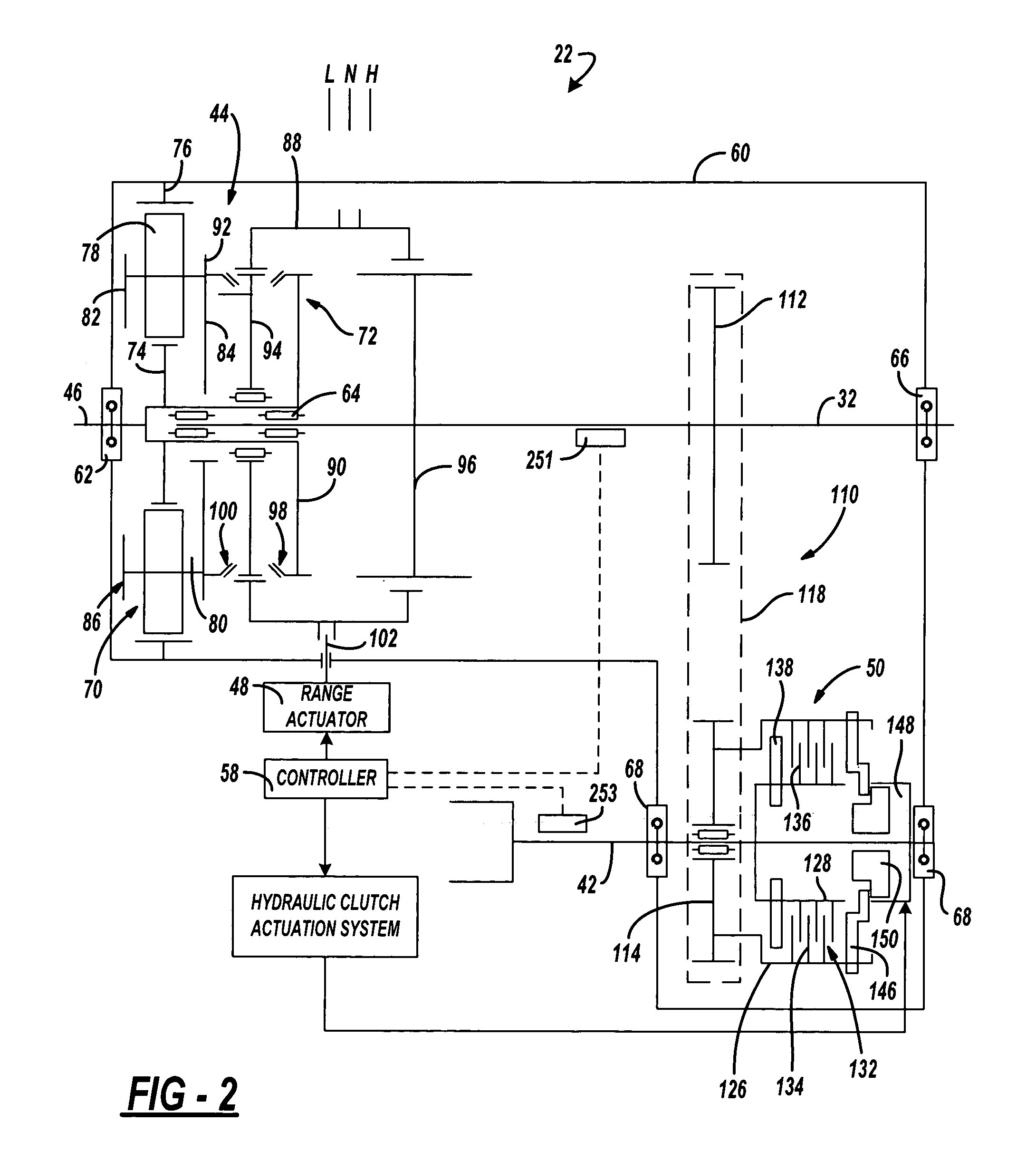
case 22
[0025]Transfer case 22 is shown schematically in FIG. 2 to include a housing 60 from which input shaft 46 is rotatably supported by bearing assembly 62. Input shaft 46 is adapted for connection to the output shaft of transmission 20. Rear output shaft 32 is also shown rotatably supported between input shaft 46 and housing 60 via bearing assemblies 64 and 66 while front output shaft 42 is rotatably supported from housing 60 by a pair of bearing assemblies 68. Range clutch 44 is shown to include a planetary gearset 70 and a synchronized range shift mechanism 72. Planetary gearset 70 includes a sun gear 74 fixed for rotation with input shaft 46, a ring gear 76 non-rotatably fixed to housing 60, and a set of planet gears 78 rotatably supported on pinion shafts 80 extending between front and rear carrier rings 82 and 84, respectively, that are interconnected to define a carrier 86.
[0026]Planetary gearset 70 functions as a two-speed reduction unit which, in conjunction with a sliding rang...
case 22 ′
[0067]Transfer case 22′ further includes a transfer clutch 50 and hydraulic clutch actuation system 120. Transfer clutch 50 includes a drum 126′ fixed for rotation with first sprocket 112′, a hub 128′ fixed for rotation with rear output shaft 32′, and a multi-plate clutch pack 132′ operably disposed therebetween. Hydraulic clutch actuation system 120′ includes a piston that can be hydraulically engaged with clutch pack 132′.
[0068]Referring now to FIG. 14, a drive axle assembly 370 is shown which is generally a modified version of rear axle assembly 26 and which incorporates a torque transfer mechanism in association with rear differential 28 so as to permit adaptive control of the torque biasing and intra-axle speed differentiation between rear wheels 24. The torque transfer mechanism is a torque bias coupling 368 shown to include a multi-plate clutch assembly 372 that is operably disposed between carrier 286 and one of axleshafts 25, and a clutch actuator system 374. Clutch assembl...
PUM
 Abstract
Description
Claims
Application Information
 - Generate Ideas
- Intellectual Property
- Life Sciences
- Materials
- Tech Scout
- Unparalleled Data Quality
- Higher Quality Content
- 60% Fewer Hallucinations
Browse by: Latest US Patents, China's latest patents, Technical Efficacy Thesaurus, Application Domain, Technology Topic, Popular Technical Reports.
© 2025 PatSnap. All rights reserved.Legal|Privacy policy|Modern Slavery Act Transparency Statement|Sitemap|About US| Contact US: help@patsnap.com