Mobile base

a mobile base and base technology, applied in the field of mobile bases, can solve the problems of increasing inconvenience to users, and inconvenience to users, and achieve the effects of saving assembly and disassembly time, rigid and stable structure, and facilitating user mounting the mobile bas

Inactive Publication Date: 2006-02-14
WANG WANG TIEN
View PDF8 Cites 14 Cited by
  • Summary
  • Abstract
  • Description
  • Claims
  • Application Information

AI Technical Summary

Benefits of technology

[0007]Another objective of the present invention is to provide a mobile base that has a simplified construction with fewer parts, thereby saving time of assembly and disassembly, and thereby facilitating the user mounting the mobile base.
[0008]A further objective of the present invention is to provide a mobile base that is assembled by a first side rack, a second side rack, a plurality of upper transverse bars, and a plurality of lower transverse bars, so that the mobile base has a rigid and stable structure.
[0009]A further objective of the present invention is to provide a mobile base, wherein the adjusting roller is hidden in the respective lower transverse bar, and the adjusting unit is hidden in a space between the first side rack and the second side rack, so that the adjusting unit is not operated unintentionally.

Problems solved by technology

However, the conventional base 12 is fixed and cannot be moved easily, thereby causing inconvenience to the user when he wishes to move the conventional base 12.
In addition, the conventional base 12 has a complicated construction with more parts, thereby increasing time of assembly and disassembly, and thereby causing inconvenience to the user when mounting the conventional base 12.

Method used


Image

  • Mobile base
  • Mobile base
  • Mobile base

Examples


Embodiment Construction

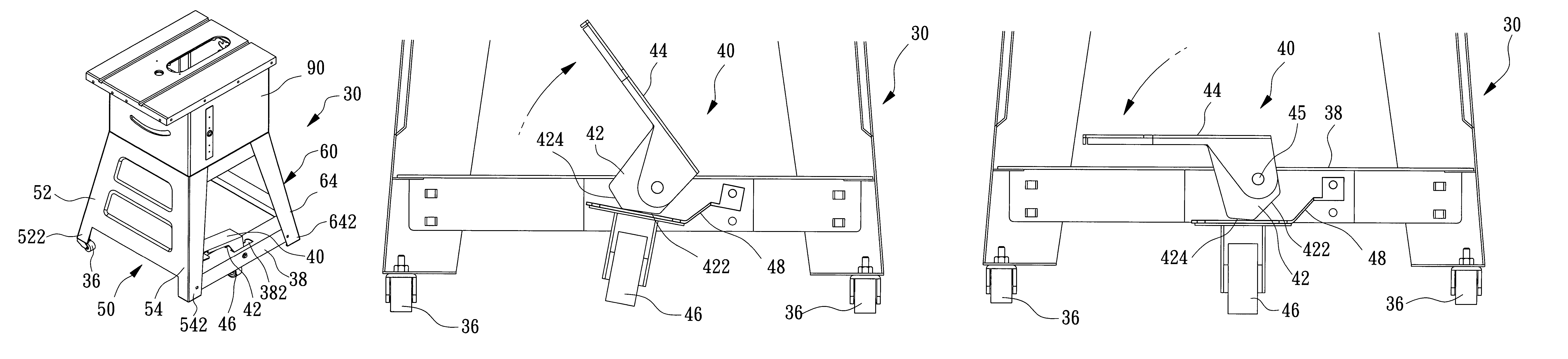
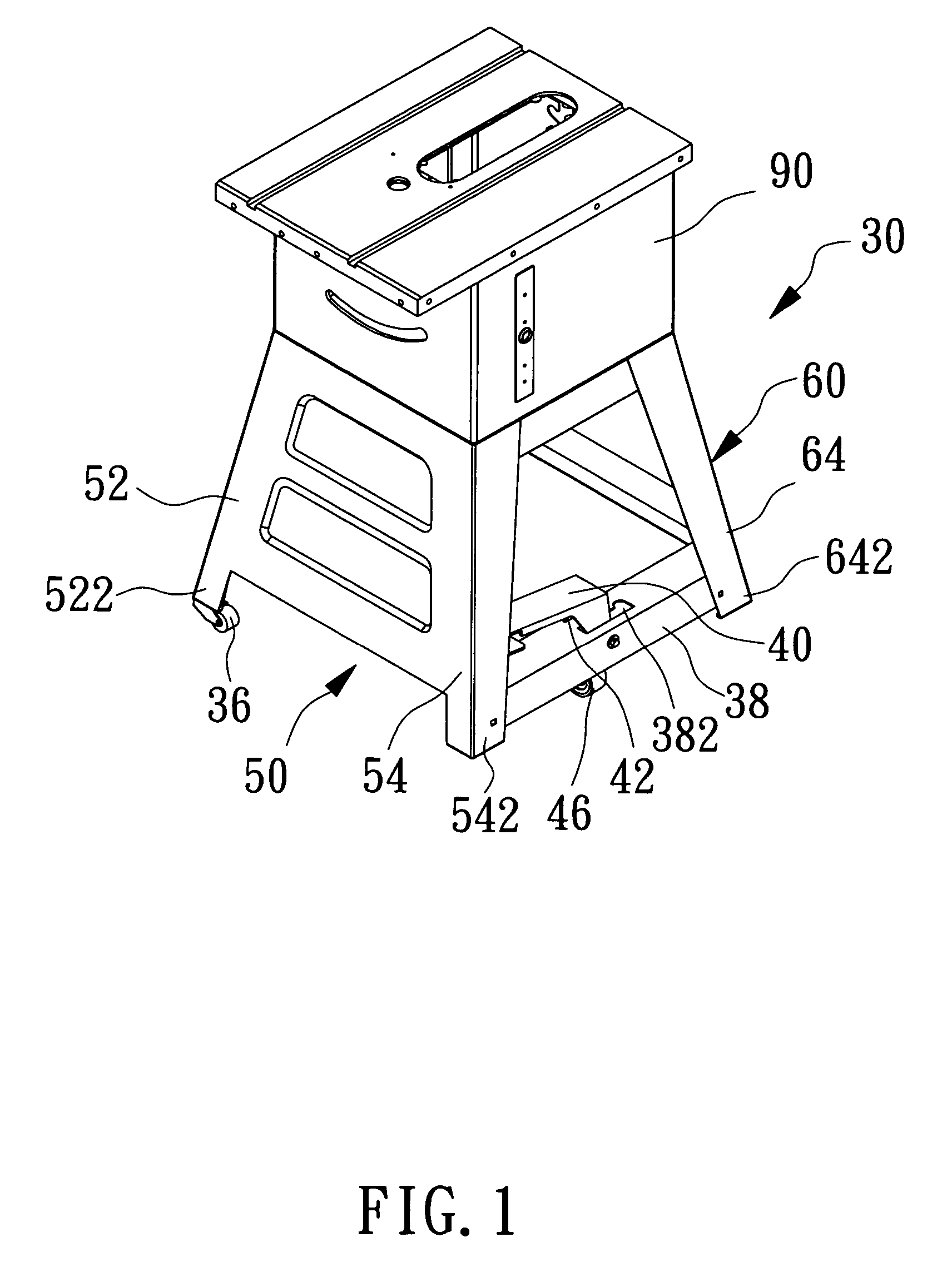
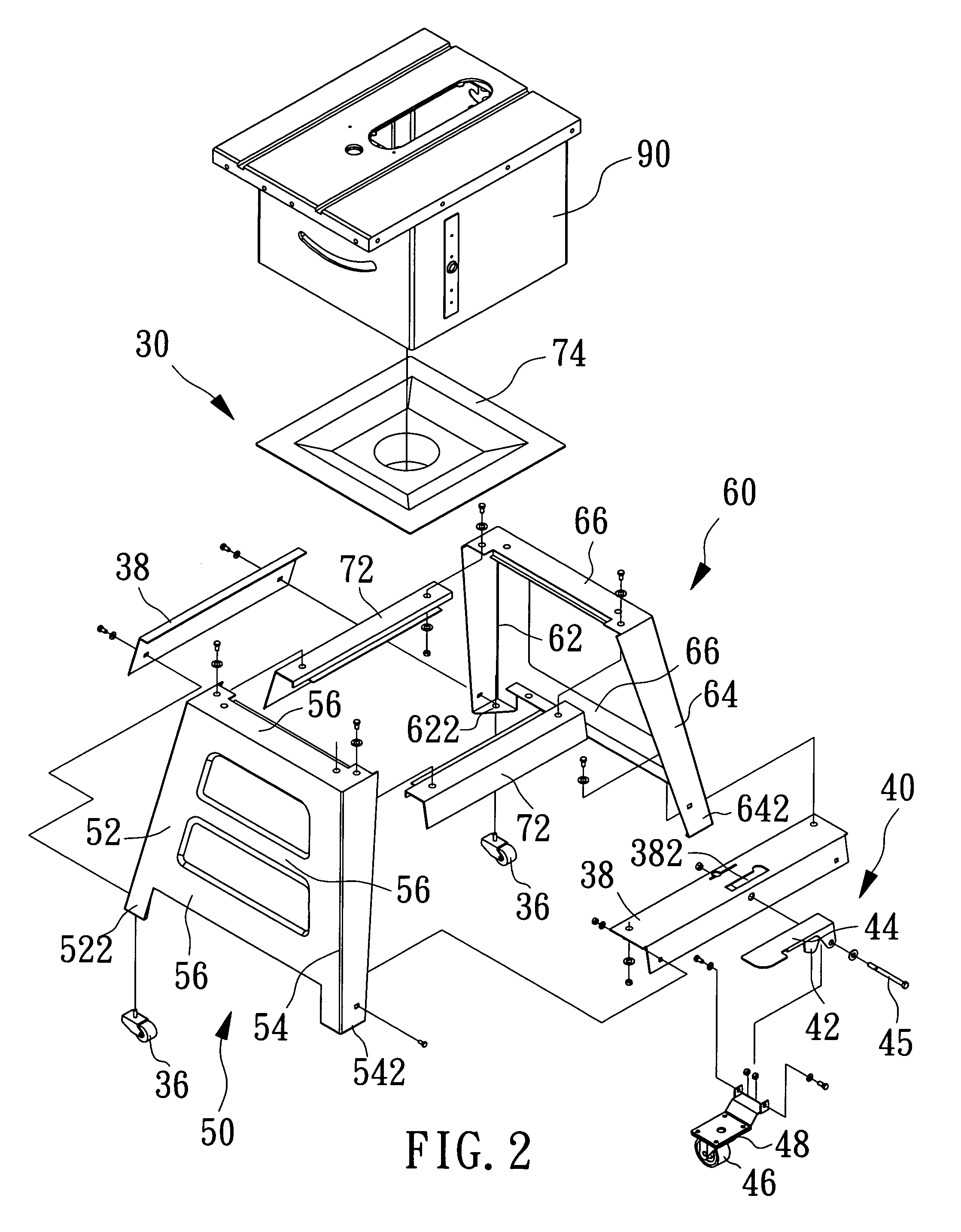
[0024]Referring to the drawings and initially to FIGS. 1–3, a mobile base 30 in accordance with the preferred embodiment of the present invention is used to support a small-size sawing table 90 and comprises a first side rack 50, a second side rack 60, a plurality of upper transverse bars 72 mounted between the first side rack 50 and the second side rack 60, and a plurality of lower transverse bars 38 mounted between the first side rack 50 and the second side rack 60.

[0025]The first side rack 50 has a first side formed with a first leg 52 having a lower end formed with a first foot portion 522 provided with a fixing roller 36 and a second side formed with a second leg 54 having a lower end formed with a second foot portion 542. The first side rack 50 includes a plurality of transverse portions 56 mounted between the first leg 52 and the second leg 54.

[0026]The second side rack 60 has a first side formed with a first leg 62 having a lower end formed with a first foot portion 622 prov...


PUM


Abstract

A mobile base includes a main body having a first side formed with two first foot portions and a second side formed with two second foot portions, two fixing rollers each mounted on a respective first foot portion, an adjusting plate mounted between the second foot portions, an adjusting roller mounted on the adjusting plate to move therewith, and an adjusting unit mounted between the second foot portions and urged on the adjusting plate to press the adjusting plate to move. Thus, the adjusting unit is hidden in a space between the first side rack and the second side rack, so that the adjusting unit is not operated unintentionally.

Description

BACKGROUND OF THE INVENTION[0001]1. Field of the Invention[0002]The present invention relates to a mobile base, and more particularly to a mobile base for a miniature tool, such as a small-size sawing table, a small-size tool machine or the like.[0003]2. Description of the Related Art[0004]A conventional base 12 in accordance with the prior art shown in FIGS. 6 and 7 is used to support a small-size sawing table 10 and comprises four upright posts 122, four upper transverse bars 14 mounted between upper portions of the four upright posts 122, and four lower transverse bars 16 mounted between lower portions of the four upright posts 122. However, the conventional base 12 is fixed and cannot be moved easily, thereby causing inconvenience to the user when he wishes to move the conventional base 12. In addition, the conventional base 12 has a complicated construction with more parts, thereby increasing time of assembly and disassembly, and thereby causing inconvenience to the user when m...

Claims


Application Information

Patent Timeline
Patent Type & Authority Patents(United States)
IPC IPC(8): B62D21/14B25H1/04B62B5/00B62B5/04
CPCB25H1/04Y10T16/1943B62B5/049
Inventor WANG, WANG TIEN
Owner WANG WANG TIEN
Why Eureka
Try Eureka