Seat device for vehicle

a seat device and vehicle technology, applied in the direction of movable seats, dismountable/non-movable seats, roofs, etc., can solve the problems of low flexibility of seat devices for vehicles when seats are in use, and the inability of storable seats to effectively use space, so as to achieve high flexibility and improve convenien

Inactive Publication Date: 2006-02-14
HONDA MOTOR CO LTD
View PDF19 Cites 47 Cited by
  • Summary
  • Abstract
  • Description
  • Claims
  • Application Information

AI Technical Summary

Benefits of technology

[0014]Therefore, it is possible to provide high flexibility when the seat cushion is in a useable position, that is, when occupants are seated, and further improvement in the convenience.
[0021]This seat device for a vehicle adopts a storable seat having the pair of link arms crossing and rotatably connected to each other, of which each one ends supports a lower surface of the second seat cushion, while each another ends is supported on the concavity. Therefore, this storable seat becomes useable by lifting the second seat cushion up above the concavity by raising the pair of link arms. On the other hand, the storable seat is stored in the concavity by lowering the second seat cushion by lowering the pair of link arms. In this way, the storable seat can easily change its positions between the useable position and the unused position by guiding the second seat cushion by the pair of link arms. Furthermore, the storable seat can use a space effectively when it is in the useable position because the storable seat is lifted up above the concavity when it is in use. In addition, as the concavity is provided on the upper floor located back side of the lower floor, a step height can be secured by the height of the upper floor. Therefore, the height of the second seat cushion in the useable position can be low, and as a result, the link arms can be smaller.
[0023]In this case, when the pair of link arms is raised from the concavity, as the one link arm is rotatably joined to a front position in the concavity, the pair of link arms approaches the front side of the concavity. Therefore, as the storable seat can be located above the front position side of the concavity, for example, in the case in which a tailgate is located behind the storable seat in the useable position, the storable seat can avoid interference with the tailgate.
[0026]In this case, at the another link arm, each of the one end slidably joined to the front part of the second seat cushion back and forth and the another end slidably joined to the rear part of the concavity back and forth, reciprocates by sliding back and forth. Therefore, when the position of the second seat cushion is changed between the raised position and the lowered position, removal operations and setup operations, etc., of a part of the storable seat becomes unnecessary. Therefore, the storable seat can change the position between the useable position and the stored position more easily.
[0028]In this case, the seat device for a vehicle can be used in both of: the first position in which the front portion of the seat cushion is supported by the front leg rising on a front location of the rail on the lower floor, and the rear portion of the seat cushion is supported by the rear leg rising on the lower floor; and a backward-use-position in which the front part of the seat cushion is supported by the front leg rising on a rear position of the rail on the first floor, and the rear portion of the seat cushion is supported on the upper floor in a condition that the rear leg is disconnected from the lower floor and is folded. Therefore, the first seat can be used, that is, the first seat can accept an occupant by changing the position back and forth, while the first seat is positioned on a boundary location between the lower floor and upper floor. In addition, when the storable seat is in use, the seat cushion is dislocated from a space above the concavity by locating the seat cushion in the first position. When the storable seat is unused, the seat cushion can be used in both of the first position, and the second position in which the seat cushion is supported above the concavity. Therefore, it is possible to obtain high flexibility when the seat (the first seat cushion) is in use (that is, when occupants are seated), and further improvement in the convenience.

Problems solved by technology

However, the seat device for a vehicles has low flexibility when the seat is in use, that is, when occupants are seated.
However, the storable seat has a problem in that the storable seat cannot use space effectively when it is in use because the storable seat cannot be used without a space outside the storage concavity.

Method used


Image

  • Seat device for vehicle
  • Seat device for vehicle
  • Seat device for vehicle

Examples


Embodiment Construction

[0034]An embodiment of a seat device for a vehicle according to the present invention will be explained below with reference to figures.

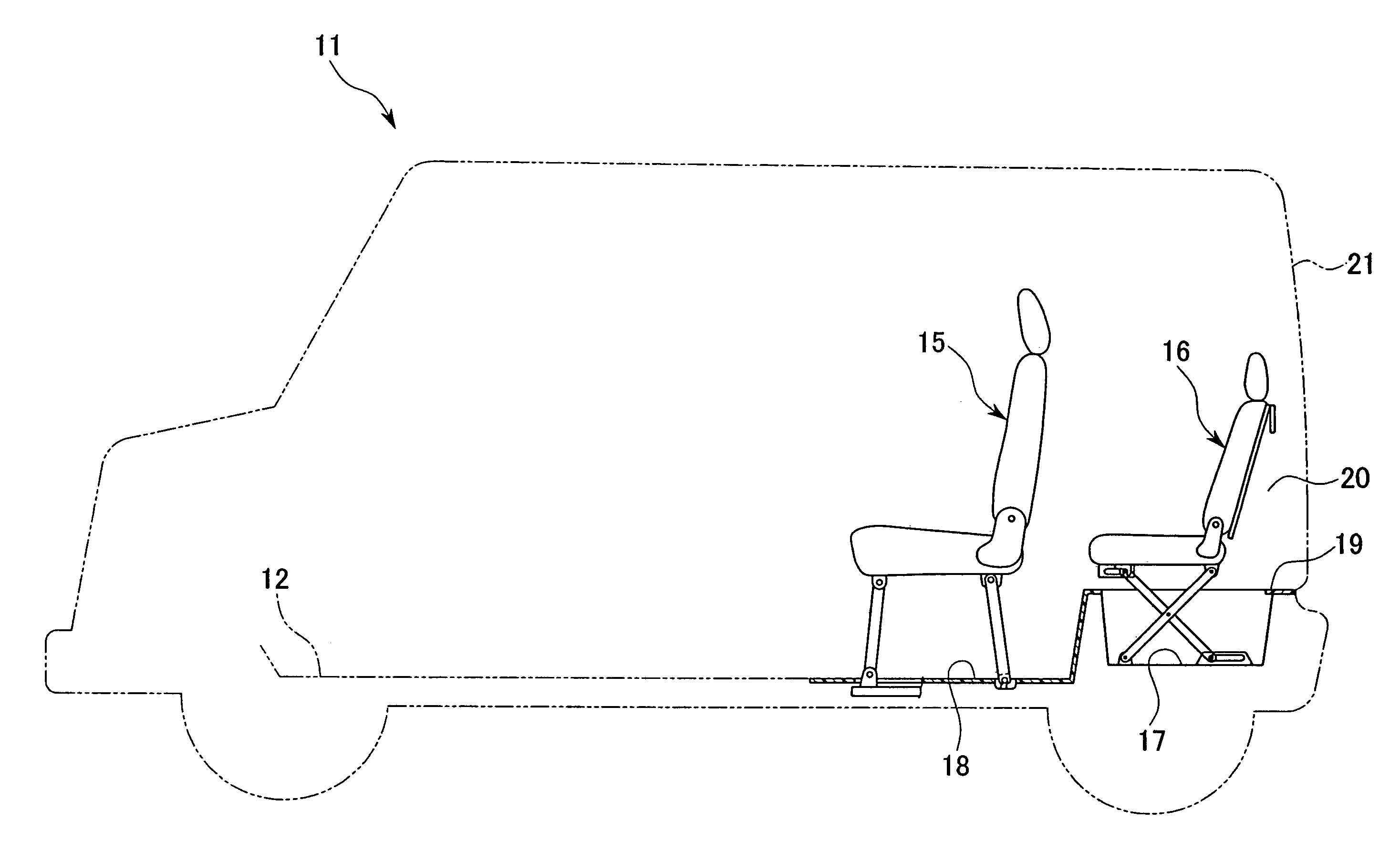
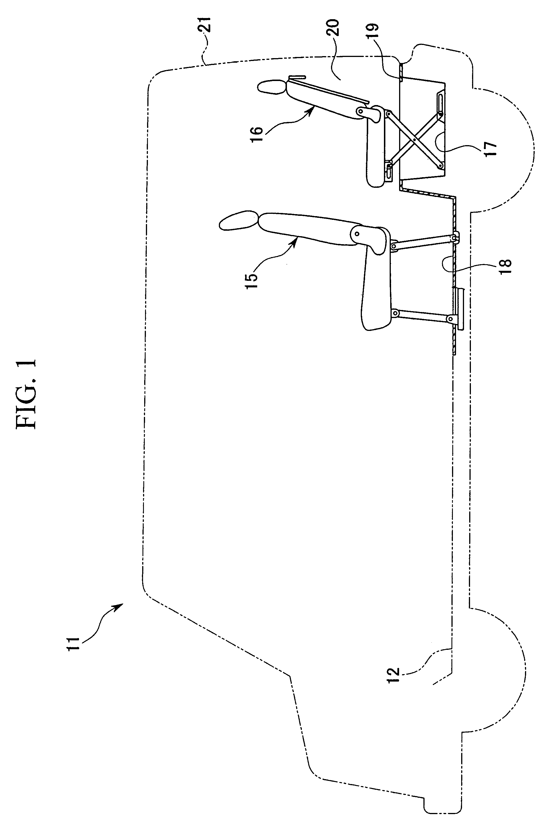
[0035]FIG. 1 shows a seat device for a vehicle 11 according to the embodiment of the present invention. The vehicle 11 is a two-box type vehicle. The vehicle 11 has a seat arrangement including a front row seat (a front side seat) 15 arranged on a floor 12, and a storable seat 16 arranged behind the front row seat 15 and being storable in a storage concavity 17 on the floor 12.

[0036]Firstly, the front row seat 15 will be explained.

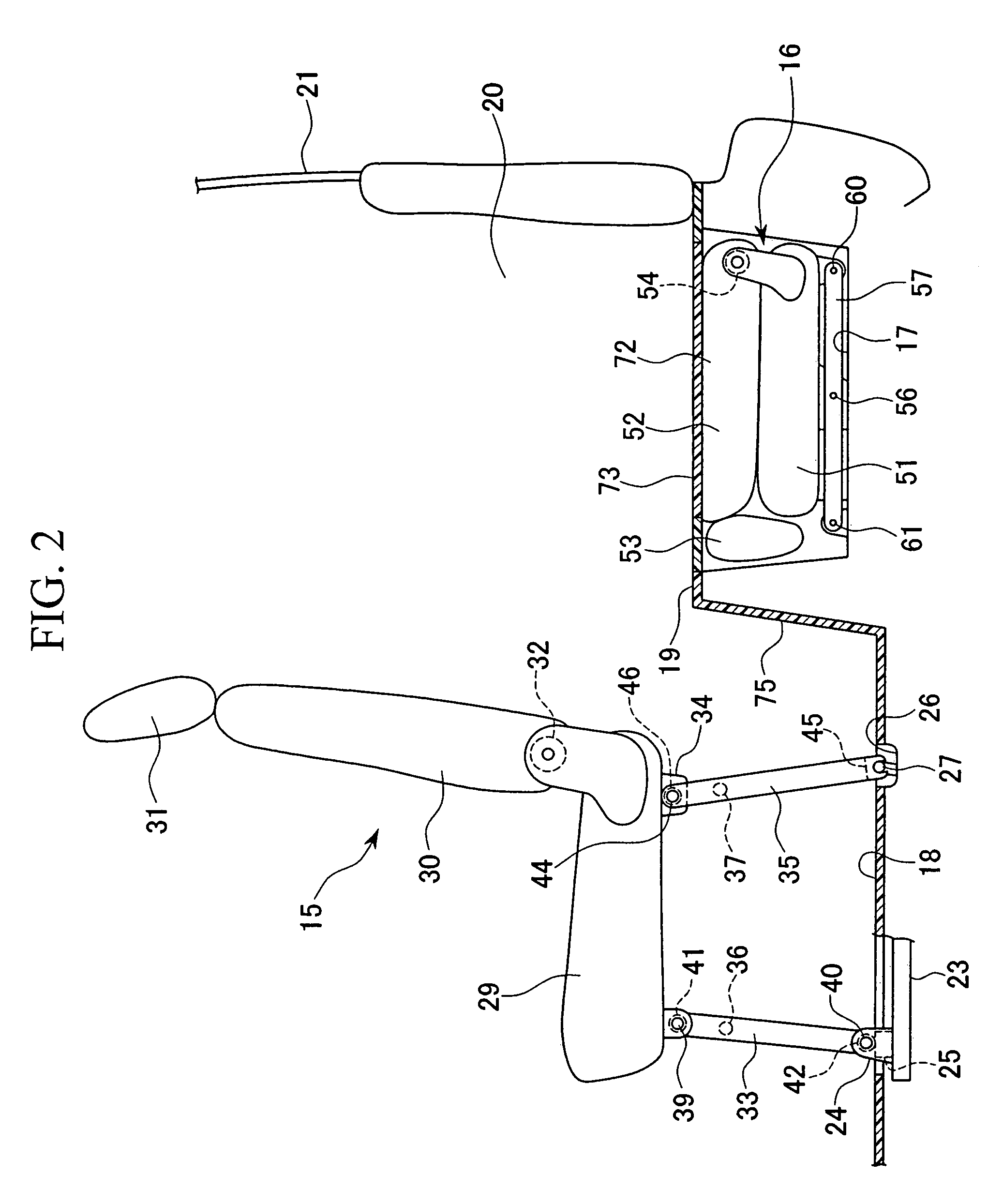
[0037]As shown in FIG. 2, a lower floor 18 on which the front row seat 15 is mounted, is connected to an upper floor 19 which is located behind the lower floor 18 and is also located higher than the lower floor 18. The space above the upper floor 19 forms a cargo space 20. An openable and closable tail gate 21 is provided behind the upper floor 19.

[0038]A pair of left-and-right rails 23 is mounted on the lower floor 18 ext...


PUM


Abstract

A seat device for a vehicle of the present invention includes a rail, a seat, a front leg, and a rear leg. The seat is made movable between a first position in which a seat cushion is supported on a lower floor via the front leg and the rear leg, and a second position in which the rear leg is disengaged from the lower floor and pivoted toward the seat cushion, a front portion of the seat cushion is supported on the lower floor via the front leg, and a rear portion of the seat cushion is supported on an upper floor.

Description

BACKGROUND OF THE INVENTION[0001]Priority is claimed on Japanese Patent Application No. 2003-278598, filed Jul. 23, 2003, and Japanese Patent Application No. 2003-278599, filed Jul. 23, 2003, the contents of which are incorporated herein by reference.[0002]1. Field of the Invention[0003]The present invention relates to a seat device for a vehicle.[0004]2. Description of Related Art[0005]For recreational vehicles, etc., various seat arrangements are used to improve convenience. For example, in the case in which a seat is positioned at a boundary location between a lower floor and an upper floor which is higher than the lower floor, a seat device for a vehicle having foldable front legs provided below a front part of a seat cushion and connected on the lower floor, and a hook provided below a rear portion of the seat cushion so that the hook can be engaged to or disengaged from a joining part on the upper floor, is disclosed (for example, refer to Japanese Unexamined Patent Applicatio...

Claims


Application Information

Patent Timeline
Patent Type & Authority Patents(United States)
IPC IPC(8): B60N2/12B60N2/30B60N2/06B60N2/36B60N2/48
CPCB60N2/065B60N2/3011B60N2/3061B60N2/3065B60N2/4858B60N2/3079B60N2/309B60N2/36B60N2/3072B60N2/859
Inventor OYAMA, RIKIYA
Owner HONDA MOTOR CO LTD
Why Eureka
Try Eureka