Sliding member

a technology of sliding member and sliding plate, which is applied in the field of sliding plate, can solve the problems of inability to achieve the effect of improving wear resistance by hard particles, lack of elongation and inferior conformability of overlay layer, and inability to achieve the effect of improving wear resistan

Inactive Publication Date: 2006-02-14
DAIDO METAL CO LTD
View PDF3 Cites 16 Cited by
  • Summary
  • Abstract
  • Description
  • Claims
  • Application Information

AI Technical Summary

Benefits of technology

[0007]An object of the invention is to provide a sliding member which uses Bi or a Bi alloy as the overlay layer while making it possible to improve wear resistance.

Problems solved by technology

In this case, if the content of the hard particles is less than 0.05 vol %, it is impossible to attain the effect of improving wear resistance by the hard particles.
If the content exceeds 25 vol %, the overlay layer exhibits lack of elongation and inferior conformability, and cracks or exfoliation are liable to occur, when it is used as a bearing, whereby the effect of improving wear resistance can not be attained.

Method used


Image

  • Sliding member
  • Sliding member

Examples


Embodiment Construction

[0025]Herein below, there will be described embodiments of the present invention.

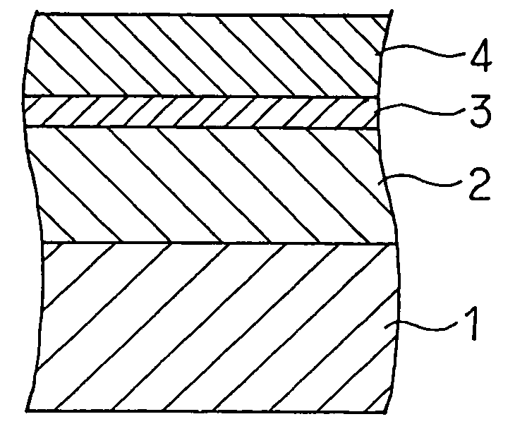
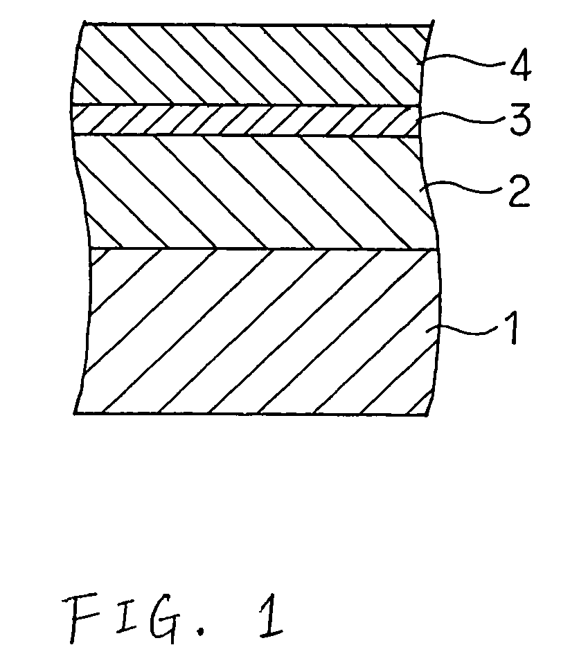
[0026]As shown in FIG. 1, a bearing alloy layer 2 made of a Cu alloy or an Al alloy was formed on a back metal layer 1 made of a steel plate, an intermediate layer 3 was formed on the bearing alloy layer 2 by electroplating, and an overlay layer 4 was formed on the intermediate layer 3 by electroplating, whereby invention specimens 1 to 6 and comparative specimens 7 to 9 were obtained as shown in following Table 1. In this case, the thickness of the intermediate layer 3 was from 0.5 to 5 μm and the thickness of the overlay layer was from 5 to 15 μm.

[0027]With regard to the intermediate layer 3, there are shown those made of an elemental Ag and of a Cu alloy. In Table 1, the numeral attached to the atomic symbol representing the intermediate layer means the content (by mass %) of the element.

[0028]The matrix of the overlay layer 4 was pure Bi, and Si3N4 and Al2O3 were used as hard particles. The overlay ...


PUM

PropertyMeasurementUnit
particle sizeaaaaaaaaaa
thicknessaaaaaaaaaa
thicknessaaaaaaaaaa

Abstract

An overlay layer is formed on a bearing alloy layer via an intermediate layer. The overlay layer consists of Bi or a Bi alloy, and 0.05 to 25 vol % of hard particles. While the overlay layer is made of Bi or a Bi alloy, wear resistance thereof can be improved by adding the hard particles.

Description

BACKGROUND OF THE INVENTION[0001]The present invention relates to a sliding member comprising an overlay layer made of Bi (bismuth) or a Bi alloy.[0002]The present invention relates to a sliding member comprising a bearing alloy layer and an overlay layer using Bi or a Bi alloy which is formed on the bearing alloy layer.[0003]In internal-combustion engines of motor vehicles, for example, there have been used sliding bearings with utilization of a copper-based or aluminum-based bearing alloy, on each of which usually an overlay layer is formed to improve conformability. The overlay layer has been conventionally made of a soft lead alloy or in some cases, an Sn alloy.[0004]However, it is preferable not to use Pb because Pb is an environmental pollution substance, if it is possible to do so. Thus, various researches and developments have been conducted heretofore, for example, there is proposed the use of Bi or a Bi alloy instead of the Pb alloy in JP-A-2001-20955.[0005]However, when t...

Claims


Application Information

Patent Timeline
Patent Type & Authority Patents(United States)
IPC IPC(8): F16C33/00B32B15/01C22C12/00C25D5/18C25D7/10C25D15/00F16C33/12
CPCB32B15/012B32B15/015C22C12/00C25D7/10F16C33/121Y10S384/912C25D15/00C25D5/18C25D5/611
Inventor KAWACHI, TOSHIAKIISHIKAWA, HIDEOSAKAMOTO, MASAAKI
Owner DAIDO METAL CO LTD
Why Eureka
Try Eureka