Stanchion and cross rail assembly

a technology of cross rails and stanchion, which is applied in the direction of loading securing, transportation and packaging, packaging, etc., can solve the problems of limiting the size and shape of articles or loads carried, posing an easy target for thieves, and operators cannot ensure that the stanchions are properly positioned and secured to the side rails

Inactive Publication Date: 2006-02-14
SPORTRACK
View PDF5 Cites 51 Cited by
  • Summary
  • Abstract
  • Description
  • Claims
  • Application Information

AI Technical Summary

Benefits of technology

[0008]A stanchion for an article carrier system is provided that comprises a main body member having cavity extending inwardly into the main body member from a plate. A floor of said cavity includes a first plurality of circumferentially spaced ramps adjacent to the floor. The stanchion further includes an arm having an end sized to rotate within the cavity. A second plurality of circumferentially spaced ramps is positioned adjacent to a bottom edge of the end. The cavity includes a bottom edge that includes a second plurality of circumferentially spaced ramps. A post is also included in the stanchion and has a first end positioned within the cavity and secured to the arm. The post also has a second end. A cleat is located adjacent to the second end. The first plurality of ramps and the second plurality of ramps are configured to raise and lower the cleat in relation to the main body member when the arm is rotated about the main body member.

Problems solved by technology

This assembly may limit the size and shape of articles or loads carried by the vehicle because the cross rails cannot be properly spaced to accommodate certain articles or loads.
While having a moveable and positionable stanchion and cross rail is advantageous for properly and safely positioning articles and loads on the vehicle, they do, however, pose an easy target for thieves.
While the “sealed” ends of the supports deter thieves from stealing the stanchions and cross rails, they may be inconvenient to the actual owners who may want to remove the stanchions and cross rails when not in use, or the actual design of the article carrier device may not lend itself to having an end of the side rail sealed by a support.
Another issue presented by the present article carrier systems and the moveable and positionable stanchions and cross rails is that an operator cannot ensure that the stanchions are properly positioned and secured to the side rails.
If the stanchions are not properly seated and secured to the side rails, the articles or loads may move and shift during transit causing the securement mechanisms used, such as rope or elastic cords, to loosen, thereby presenting the possibility that the load or article may be lost on the highway or road, thus leading to a loss of property as well as safety concerns.
There is no way to ensure that the stanchions are properly seated without a physical check.

Method used


Image

  • Stanchion and cross rail assembly
  • Stanchion and cross rail assembly
  • Stanchion and cross rail assembly

Examples


Embodiment Construction

[0021]Referring now to the drawings, a preferred illustrative embodiment of the present invention is shown in detail. Although the drawings represent an embodiment of the present invention, the drawings are not necessarily to scale and certain features may be exaggerated to better illustrate and explain the present invention. Further, the embodiment set forth herein is not intended to be exhaustive or otherwise to limit or restrict the invention to the precise forms and configurations shown in the drawings and disclosed in the following detailed description.

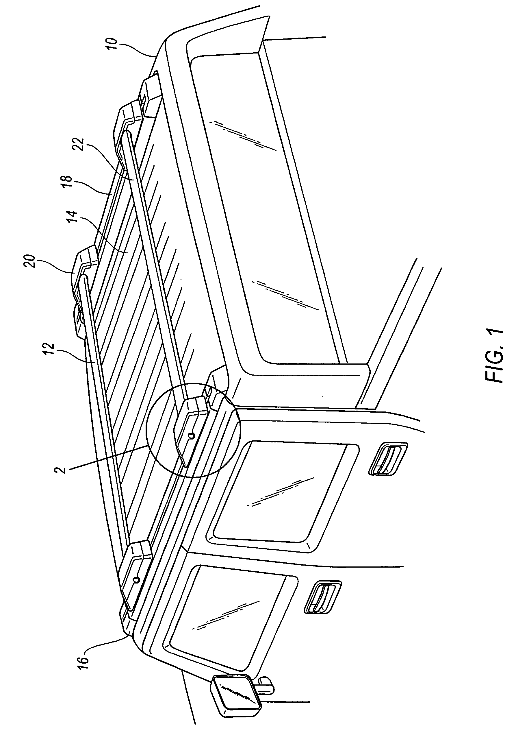
[0022]A motor vehicle 10 is illustrated in FIG. 1 having an article carrier system 12 secured to a roof 14 of vehicle 10. Article carrier system 12 comprises four supports 16, secured respectively adjacent to each of four corners of roof 14. A pair of side rails 18 extend generally from the front to the rear of vehicle 10, each side rail being disposed between two supports 16. Article carrier system 12 further includes stanchions...


PUM


Abstract

A stanchion for an article carrier system comprises a main body member having a cavity extending inwardly of the main body member from a plate. A floor of said cavity includes a first plurality of circumferentially spaced ramps. The stanchion further includes an arm having an end sized to rotate within the cavity. The cavity includes a bottom edge that includes a second plurality of circumferentially spaced ramps. A post is also included in the stanchion and has a first end positioned within the cavity and secured to the arm. The post also has a second end that includes a cleat. The first plurality of ramps and the second plurality of ramps are configured to cooperate to raise and lower the cleat in relation to the main body member when the arm is rotated about the main body member.

Description

FIELD OF THE INVENTION[0001]The present invention relates generally to article carrier systems for motor vehicles and, more particularly, to a stanchion for positioning and securing cross rails in various locations in the article carrier system.BACKGROUND OF THE INVENTION[0002]Article carrier systems are well known throughout the automotive industry for use in storing or retaining luggage, bicycles, small boats, or the like on the exterior of a motor vehicle even while in motion. Typically, article carrier systems include a number of individual components such as supports, side rails, stanchions, cross rails, and the like. Generally, in a roof mounted carrier system, a support is secured to each of the four corners of a vehicle roof. A side rail is positioned in between and secured to two of the four supports in a manner such that two side rails are essentially parallel to one another and extend between the front and the rear of the vehicle. Stanchions may then be attached to the si...

Claims


Application Information

Patent Timeline
Patent Type & Authority Patents(United States)
IPC IPC(8): B60P7/08
CPCB60R9/058B60R9/045
Inventor SAWARD, RONALD G.
Owner SPORTRACK
Why Eureka
Try Eureka