Connector for use with a medical catheter and medical catheter assembly

a technology for connecting devices and medical catheters, which is applied in the field of medical catheters, can solve problems such as unsuitable long-term, unsatisfactory long-term, and inability to take food and/or medications transorally

Inactive Publication Date: 2006-02-14
BOSTON SCI SCIMED INC
View PDF9 Cites 18 Cited by
  • Summary
  • Abstract
  • Description
  • Claims
  • Application Information

AI Technical Summary

Problems solved by technology

Certain patients are unable to take food and / or medications transorally due to an inability to swallow.
Although the intravenous administration of food and / or medications to such patients may be a viable short-term approach, it is not well-suited for the long-term.
Otherwise, the gastrostomy feeding tube may separate from the dilator prior to emergence of the feeding tube from the patient, thereby requiring the feeding tube to be retrieved from the patient and possibly leading to undesired complications.
Historically, however, this standard has not typically been met by the conventional type of connection used to couple a dilator to a gastrostomy feeding tube.
In addition to failing frequently to meet the minimum tensile strength required for a connection between a dilator and a feeding tube, other shortcomings with the above-described connection are (i) that the application of the shrink-wrapped length of tubing to the assembly requires the expenditure of time and labor, (ii) that the shrink-wrapped tubing undesirably increases the cross-sectional profile of the assembly, and (iii) that there is a perception that the ends of the shrink-wrapped tubing, which ends do not lie flush with the dilator or the feeding tube, may snag tissue as the assembly makes its winding path through the patient.

Method used


Image

  • Connector for use with a medical catheter and medical catheter assembly
  • Connector for use with a medical catheter and medical catheter assembly
  • Connector for use with a medical catheter and medical catheter assembly

Examples


first embodiment

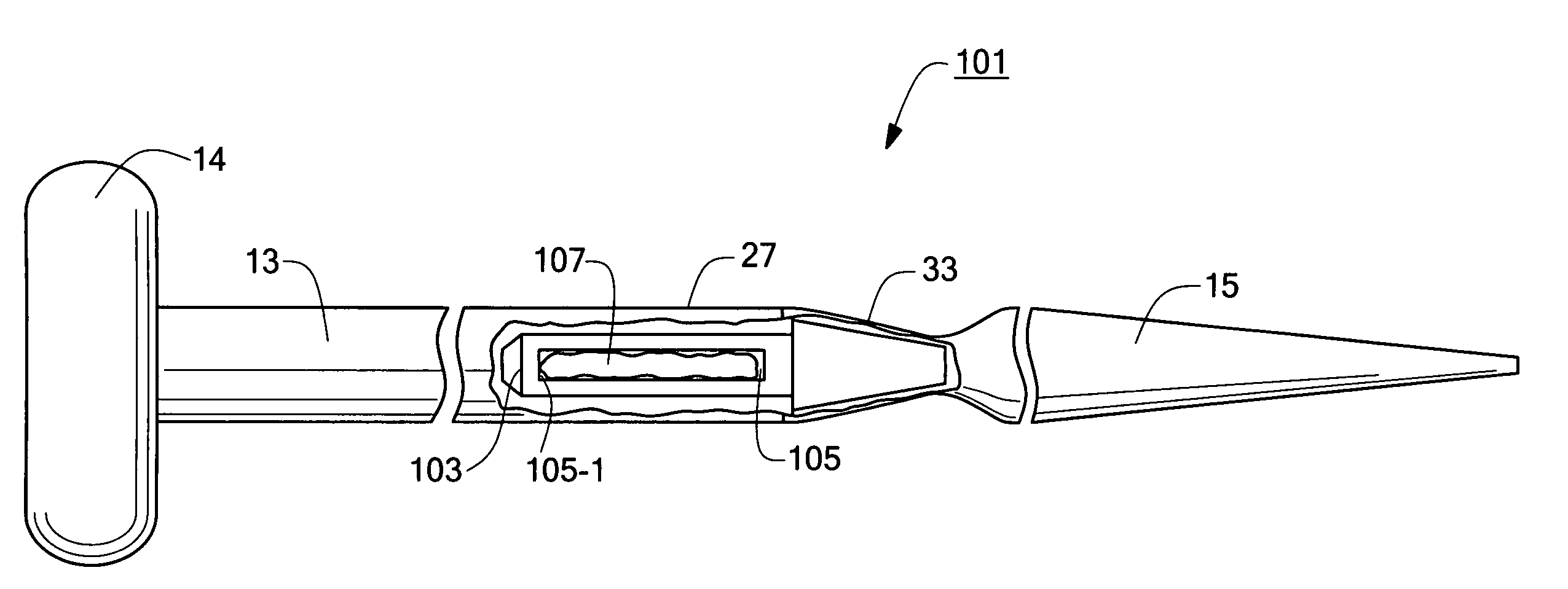
[0052]Referring now to FIG. 4, there is shown a fragmentary, side view, broken away in part, of a medical catheter assembly constructed according to teachings of the present invention and adapted for percutaneous endoscopic implantation in a patient using the push method, said medical catheter assembly being represented generally by reference numeral 101.

[0053]Assembly 101, which is shown prior to use on a patient, is similar in many respects to assembly 11, assembly 101 likewise comprising a gastrostomy feeding tube 13, an internal bolster 14 and a dilator 15. Assembly 101 differs from assembly 11, however, in that assembly 101 does not include the combination of connector 17 and tubing 19 for interconnecting tube 13 and dilator 15. Instead, assembly 101 comprises, as a means for interconnecting tube 13 and dilator 15, the combination of a connector 103, a length of silicone tubing 105 mounted within connector 103, and a quantity of silicone glue 107 (e.g., Nusil's MED 4860) applie...

second embodiment

[0065]Referring now to FIG. 8, there is shown a fragmentary, side view, broken away in part, of a medical catheter assembly constructed according to teachings of the present invention and adapted for percutaneous endoscopic implantation in a patient using the push method, said medical catheter assembly being represented generally by reference numeral 301.

[0066]Assembly 301, which is shown prior to use on a patient, is similar in most respects to assembly 101, the principal difference between the two assemblies being that assembly 301 comprises a connector 303, instead of connector 103.

[0067]Referring now to FIGS. 9(a) through 9(d), there are shown various isolated views of connector 303. Connector 303, which is a unitary member preferably made of molded plastic, is shaped to include a rear portion 310 and a front portion 315. Rear portion 310, in turn, comprises a rearward section 311 and a forward section 313. Rearward section 311, which is inserted into leading end 27 of tube 13, ...

third embodiment

[0071]Referring now to FIG. 10, there is shown a fragmentary, section view of a medical catheter assembly constructed according to the teachings of the present invention and adapted for percutaneous endoscopic implantation in a patient using the push method, said medical catheter assembly being represented generally by reference numeral 401.

[0072]Assembly 401, which is shown prior to use on a patient, is similar in many respects to assembly 101, the principal difference between the two assemblies being that assembly 401 does not include the combination of connector 103, tubing 105 and silicone glue 107 to interconnect tube 13 and dilator 15. Instead, assembly 401 comprises, as a means for interconnecting tube 13 and dilator 15, the combination of a connector 403 and a quantity of silicone glue 405 applied to connector 403 in the manner hereinafter described.

[0073]Referring now to FIGS. 11(a) through 11(d), there are shown various isolated views of connector 403. Connector 403, which...


PUM


Abstract

Connector for use with a medical catheter assembly and medical catheter assembly including the connector. In one embodiment, the connector comprises a rear portion, an intermediate portion, and a front portion. The rear portion is frusto-conical in shape and tapers rearwardly in cross-sectional diameter from its front end. A centrally-disposed, smaller-diameter, longitudinal bore is provided in the rear portion, the bore being appropriately dimensioned to receive a guidewire therethrough. The intermediate portion is generally cylindrical and is shaped to include a centrally-disposed, larger-diameter longitudinal bore and a pair of longitudinally-extending slots providing access to the larger-diameter bore. The front portion is frusto-conical in shape and tapers forwardly in cross-sectional diameter from its rear end. In use, a silicone tube is inserted into the larger-diameter bore of the intermediate portion, and the rear and intermediate portions of the connector are inserted into a gastrostomy feeding tube. A silicone glue is then used to bond the silicone tube to the gastrostomy feeding tube. The front end of the connector is inserted into a dilator and is secured thereto by spin-welding.

Description

BACKGROUND OF THE INVENTION[0001]The present invention relates generally to medical catheters, such as gastrostomy feeding tubes, and relates more particularly to medical catheter assemblies, such as percutaneous endoscopic gastrostomy (PEG) devices.[0002]Certain patients are unable to take food and / or medications transorally due to an inability to swallow. Such an inability to swallow may be due to a variety of reasons, such as esophageal cancer, neurological impairment and the like. Although the intravenous administration of food and / or medications to such patients may be a viable short-term approach, it is not well-suited for the long-term. Accordingly, the most common approach to the long-term feeding of such patients involves gastrostomy, i.e., the creation of a feeding tract or stoma between the stomach and the upper abdominal wall. Feeding is then typically performed by administering food through a catheter or feeding tube that has been inserted into the feeding tract, with t...

Claims


Application Information

Patent Timeline
Patent Type & Authority Patents(United States)
IPC IPC(8): A61M29/00A61B17/34A61J15/00A61M25/00
CPCA61B17/3415A61M25/0014A61J15/0019A61J15/0026A61J15/0034
Inventor WESTSTRATE, PATRICE A.HOLMES, JOHN C.
Owner BOSTON SCI SCIMED INC
Why Eureka
Try Eureka