Element for a color flat panel display

Inactive Publication Date: 2006-02-14
MERIDIAN SOLAR & DISPLAY
View PDF6 Cites 1 Cited by
  • Summary
  • Abstract
  • Description
  • Claims
  • Application Information

AI Technical Summary

Benefits of technology

[0041]Accordingly, an object of the present invention is to provide a color flat panel display which substantially eliminates halation problems caused by the reentry of scattered electrons from the fluorescent layer of a display device involving the use of the electron beam, and which has a high degree of contrast by using a forming material such as iron or nickel instead of the conventional carbon or boron on a fluorescent layer laminated on a glass face plate.

Problems solved by technology

Therefore, it is impossible to fabricate a television picture receiver of the thin type.
However, these devices have some problems, such as brightness, contrast, and color reproductibility when compared to the cathode-ray tube.
Therefore, the contrast of the display device is reduced, a clear image cannot be obtained, and the functions of the display can become a big problem.
However, the above patents are not capable of effectively solving the halation problem.

Method used


Image

  • Element for a color flat panel display
  • Element for a color flat panel display
  • Element for a color flat panel display

Examples


first embodiment

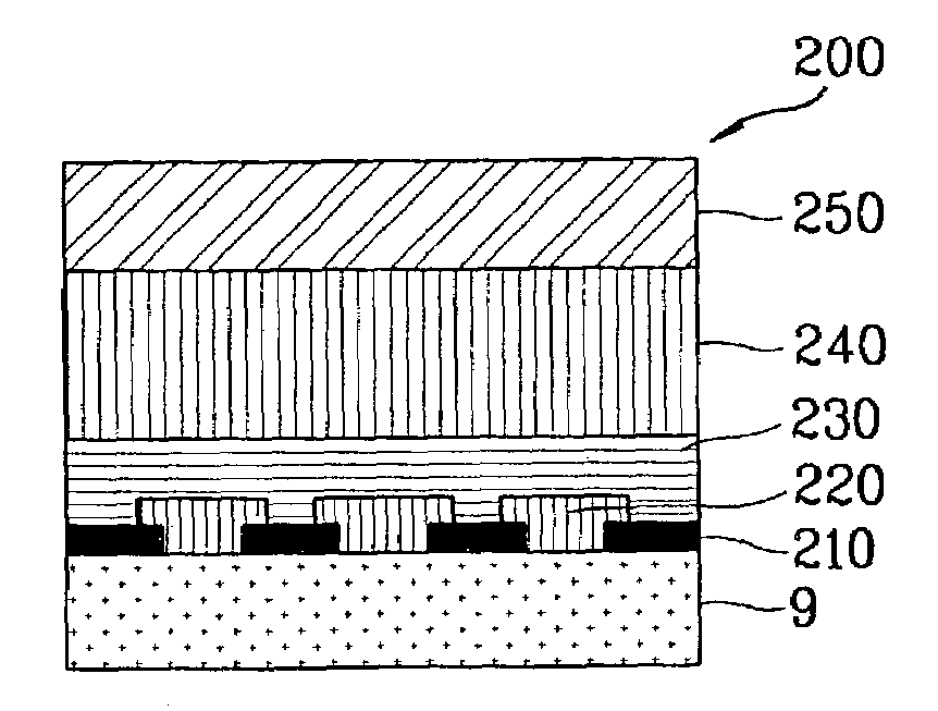
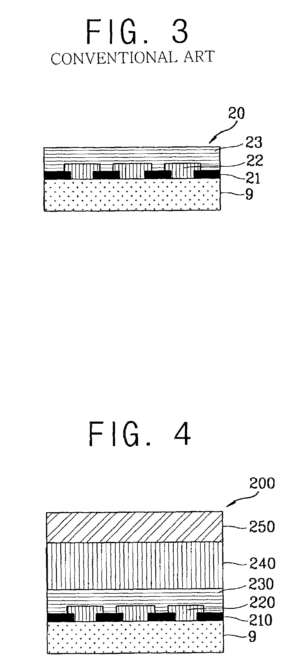
[0056]As shown in FIG. 4, the screen of a first embodiment according to the present invention comprises: a graphite layer 210 and a fluorescent layer 220 on a face plate 9 of glass material; a resin film layer 230 applied to the fluorescent layer 220; an aluminum layer 240 applied on the resin layer 230; and an iron 250 applied to the aluminum layer 240.

second embodiment

[0057]As shown in FIG. 5, the screen of a second embodiment according to the present invention comprises: a graphite layer 210 and a fluorescent layer 220 on a face plate 9 of glass material; a resin film layer 230 applied to the fluorescent layer 220; an aluminum layer 240 applied to the resin layer 230; and a nickel 260 applied to the aluminum layer 240.

[0058]The iron layer 250 and the nickel layer 260 can be replaced with a chromium layer.

[0059]Hereinafter, embodiments of the method for fabricating the screen 200, that is, the color flat panel display element, will be described in detail.

[0060]As a first embodiment of the method for fabricating the screen 200, the screen 200 shown in FIG. 4 and FIG. 5 is formed by laminating the fluorescent layer 220 on the graphite layer 210 which is laminated on the face plate 9. The resin film layer 230 is laminated on the fluorescent layer 220 and the aluminum layer 240 is formed on the resin film layers 230 using an evaporating method or a s...

third embodiment

[0065]As shown in FIG. 7, in the method for fabricating the screen 200, the graphite layer 210 is laminated on the face plate 9 made of a glass material, the fluorescent layer 220 is laminated on the graphite layer 210, the resin film layer 230 is laminated on the fluorescent layer 220, and the aluminum layer 240 and the iron 250 or the nickel 260 which will be laminated thereon are successively formed using a pellet 700 which is clad with aluminum and iron, aluminum and nickel, or aluminum and chromium (not shown) by the evaporating method or the sputtering method.

[0066]In the screen 200, including the layer for preventing electron reentry and fabricated in above matter, the reentry of secondary electron toward the screen plate which is generated when the electron beam becomes incident to the screen 200, can be prevented by utilizing a metal layer such as iron 250, nickel 260, or chromium (not shown). Accordingly, the halation phenomenon can be prevented while utilizing a thinner a...


PUM


Abstract

A screen composite provided on a face plate of a flat panel display device, said screen composite containing an aluminum layer and a metal layer formed on said aluminum layer for substantially reducing a halation phenomenon.

Description

BACKGROUND OF THE INVENTION[0001]This application claims the benefit of the Korean Application No. 2002-0029972 filed on May 29, 2002, which is hereby incorporated by reference.[0002]1. Field of the Invention[0003]The present invention relates to a color flat panel display, and more particularly, to an element for a color flat panel display which provides good image quality with a high contrast property by forming a reflecting layer on the display device, which is applied to the inner surface of a face plate, using a new metal material to remove halation caused by the reentry of scattered electrons from the rear surface of the fluorescent layer in the case of a display device using an electron beam.[0004]2. Description of the Background Art[0005]Generally, a cathode-ray tube (Brown tube) is mainly used as an image display device for color television. However, the cathode-ray tube has a very deep depth compared to the size of the front surface of the screen, caused by the structural ...

Claims


Application Information

Patent Timeline
IPC IPC(8): H01J29/10H01J9/22H01J29/18H01J29/28H01J31/12
CPCH01J29/28H01J29/185H01J29/18
Inventor RYU, SANG-CHUL
Owner MERIDIAN SOLAR & DISPLAY
Why Eureka
Try Eureka