
Low visual impact monopole tower for wireless communications

a wireless communication and low visual impact technology, applied in the direction of individual energised antenna arrays, instruments, polarisation/directional diversity, etc., can solve the problems of difficult physical relocation or replacement, interruption of wireless communications service, and inconvenient aesthetically pleasing

Inactive Publication Date: 2006-02-14
ANDREW LLC
View PDF54 Cites 34 Cited by
  • Summary
  • Abstract
  • Description
  • Claims
  • Application Information

AI Technical Summary

Problems solved by technology

However, such physical relocation or replacement is difficult.
Not only is this costly, but wireless communications service is interrupted while the manual adjustment of the downtilt is being performed.
Conventional monopole towers with triangular support platforms have an appearance that, while less objectionable than lattice-type towers, is not aesthetically pleasing.
As a result, permission to erect an unsightly monopole tower may be difficult to obtain in urban and suburban venues.
However, such camouflaging structures are impractical, difficult and expensive to construct, and costly to maintain.
Because suitable sites are increasingly difficult to secure, more complex and visually objectionable antenna arrangements are being deployed to

Method used


Image

  • Low visual impact monopole tower for wireless communications
  • Low visual impact monopole tower for wireless communications
  • Low visual impact monopole tower for wireless communications

Examples


Embodiment Construction

[0020]The invention is directed to an antenna system for wireless communications systems and, more particularly, to a monopole-mounted antenna system having an electrically-adjustable main beam direction and constituent antennas arranged side-by-side about a monopole tower so as to reduce the visual impact of the composite structure. Although the invention will be described next in connection with certain embodiments, it will be understood that the invention is not limited to those particular embodiments. On the contrary, the description of the invention is intended to cover all alternatives, modifications, and equivalent arrangements as may be included within the spirit and scope of the invention as defined by the appended claims.

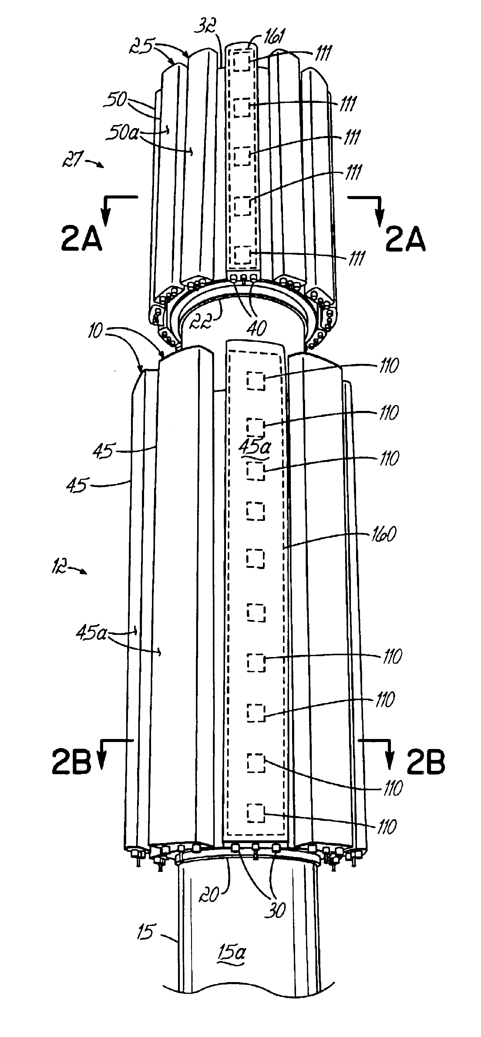
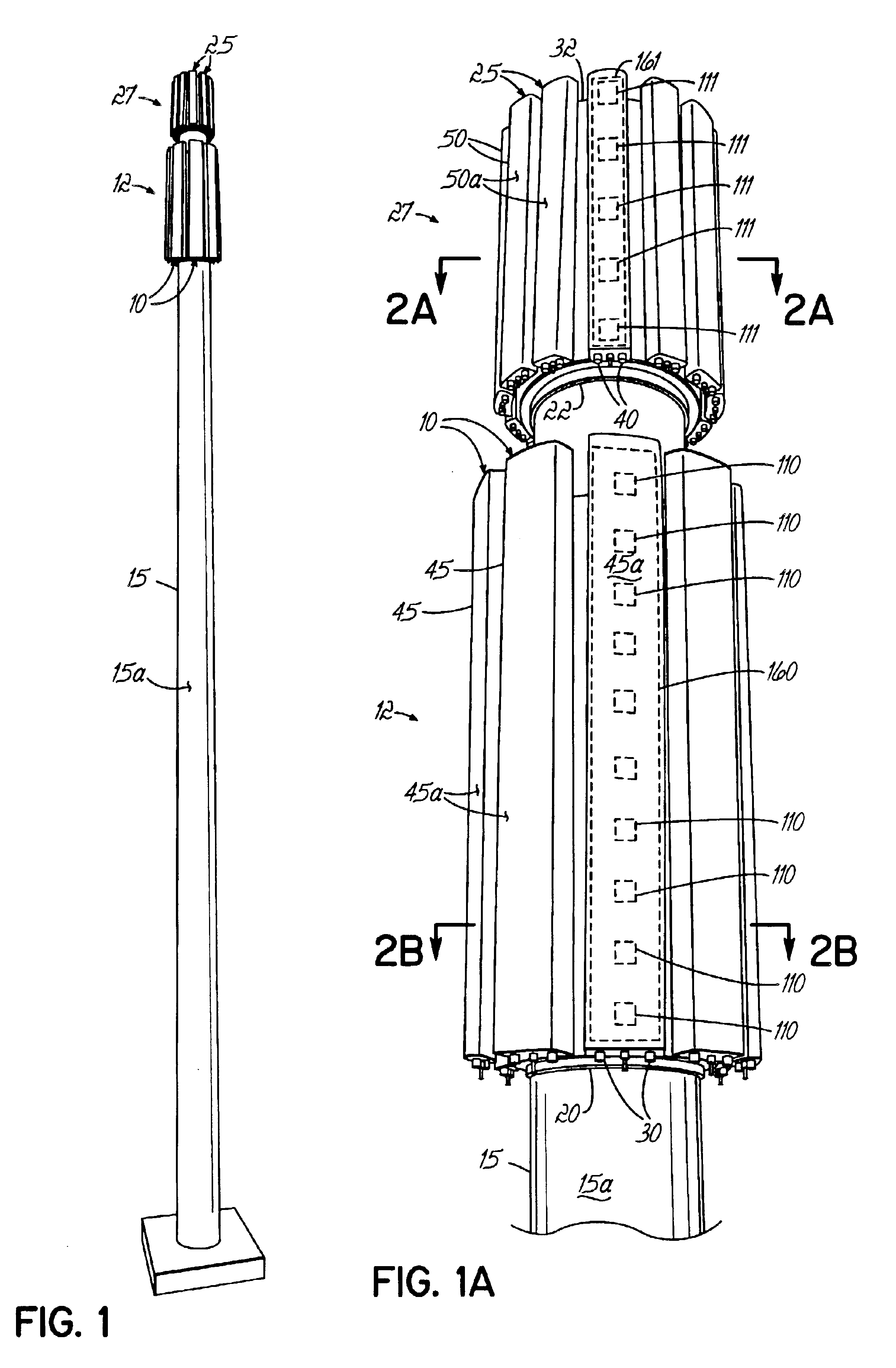
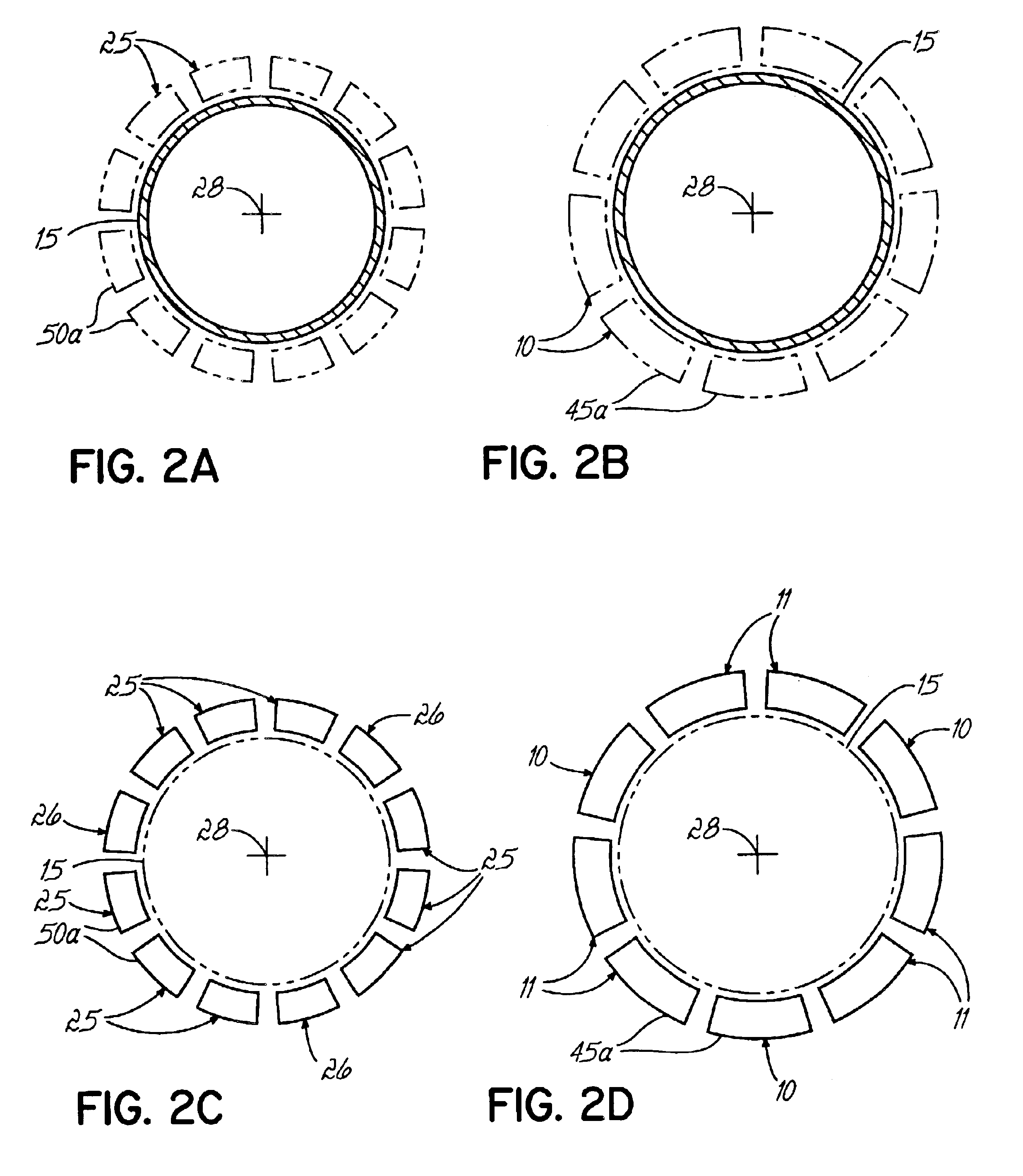
[0021]With reference to FIGS. 1 and 1A, an antenna system according to the principles of the invention includes a monopole tower 15, a plurality of, for example, twelve antennas 10, arranged in a tier or group 12 about a circumference of the monopole tower...


PUM


Abstract

An antenna system incorporating at least two antennas circumferentially arranged with a side-by-side relationship about a monopole tower. The main beam direction of the radiation pattern emanating from each antenna may be remotely adjusted in elevation and/or azimuth. The main beam direction of the radiation pattern emanating from adjacent antennas may be varied independently. The antennas may be partitioned in one or more vertically-spaced groups each of which is arranged about a circumference of the monopole tower.

Description

FIELD OF THE INVENTION[0001]The present invention relates generally to wireless communications systems and, more particularly, to a monopole-mounted antenna system in which constituent antennas are arranged circumferentially about a monopole tower such that the visual impact is reduced and in which the individual antennas have a remote electrically-adjustable main beam direction.BACKGROUND OF THE INVENTION[0002]Antenna towers have long been used for supporting antennas used in wireless communication networks, such as cellular communications systems. One common type of antenna tower is constructed of an interconnected lattice framework of steel beams. Another common type of antenna tower is a monopole tower consisting of a single tubular mast or pole extending upwardly from ground level. Monopole towers have grown in popularity because the visual impact of monopole towers is less than that of lattice-type towers and because of the relatively low cost as compared with lattice-type tow...

Claims


Application Information

Patent Timeline
IPC IPC(8): H01Q1/12G06F9/00H01Q3/30H01Q1/06H01Q1/24H01Q1/42H01Q9/34H01Q13/12H01Q21/08H01Q21/20H01Q21/30H04B1/00H04B7/08H04B7/10
CPCH01Q1/1207H01Q1/1242H01Q3/26H01Q1/44H01Q1/246H01Q13/12
Inventor DEARNLEY, RUSSELL W.ELLIOT, BOB
Owner ANDREW LLC
Learn More