Multi-beam source

a beam source and beam technology, applied in the field of beam source, can solve the problems of blurry pattern or image, image aberration, distortion, etc., and achieve the effect of reducing the various aberration effects and reducing the spread of angl

Active Publication Date: 2012-05-22
IMS NANOFABTION
View PDF15 Cites 54 Cited by
  • Summary
  • Abstract
  • Description
  • Claims
  • Application Information

AI Technical Summary

Benefits of technology

[0013]The present invention provides a multi-beam source producing a set of particle beamlets with low emittance and homogeneous current distribution, the multi-beam source being adapted to reduce the various aberration effects present in existing multi-beam applications. Emittance here denotes a measure of the parallelism of a beam, a low-emittance particle beam is a beam where all individual beamlets seem to emerge from a common virtual source not significantly larger than the virtual source of an individual beam, which means that the beamlets are emerging from a small area, or, in case of a telecentric beam, are substantially parallel (virtual source infinitely far away). Beamlets with a low emittance thus have small components of transverse velocity and a reduced spread in angle relative to an axis of propagation. It is another goal of the present invention to provide a multi-beam source which is correctable / controllable with respect to deviations from the ideal angles of the beamlets to compensate imaging errors of consecutive lens systems, as for a example a projection system or multi-lens array.

Problems solved by technology

However these systems have certain drawbacks since optical systems, regardless of whether they are light-optical or particle-optical systems, produce imaging aberrations and distortions.
Therefore sub-beams projected on the target will get blurred and the spot size of the sub-beam is no longer well-defined, which results in a blurry pattern or image.
It is not possible by means of annular electrodes alone to achieve a lens of negative refracting power; on the contrary, it is necessary to use a plate or control grid electrode through which the beam passes.
In the outer regions of the mask this would lead to image defects, especially if used in conjunction with a large reduction optical system (such as described in U.S. Pat. No. 6,768,125) where the angular errors at the object plane (aperture plate system) lead to significant landing angle errors at the substrate, or if used in conjunction with a parallel multi-column array, where the angular alignment of each beam in each column is very critical.
One solution for avoiding these shadow effects is the production of structure orifices which are inclined accordingly with respect to the axis; however this is extremely expensive from the technology point of view.
Van Bruggen et. al. aim on compensating for both the third-order geometric and first-order chromatic aberration inherent in the system, however such a system can not provide for correction of the individual beams and aberrations due to insufficient illumination of the aperture plate.
However this solution has the significant drawback of requiring specifically shaped lens arrays, e.g. convex plates or stacks of multiple plates allotting inclined holes to account for the slope of the beamlets.
Furthermore the lens arrays can scarcely be adapted to changing circumstances concerning the beamlets.

Method used


Image

  • Multi-beam source
  • Multi-beam source
  • Multi-beam source

Examples


Embodiment Construction

[0070]It should be appreciated that the invention is not restricted to the embodiments discussed in the following, which merely represent possible implementations of the invention. Generally it has to be said that the embodiments depicted here are only some of many different embodiments possible and are thus not intended to restrict the scope of the invention.

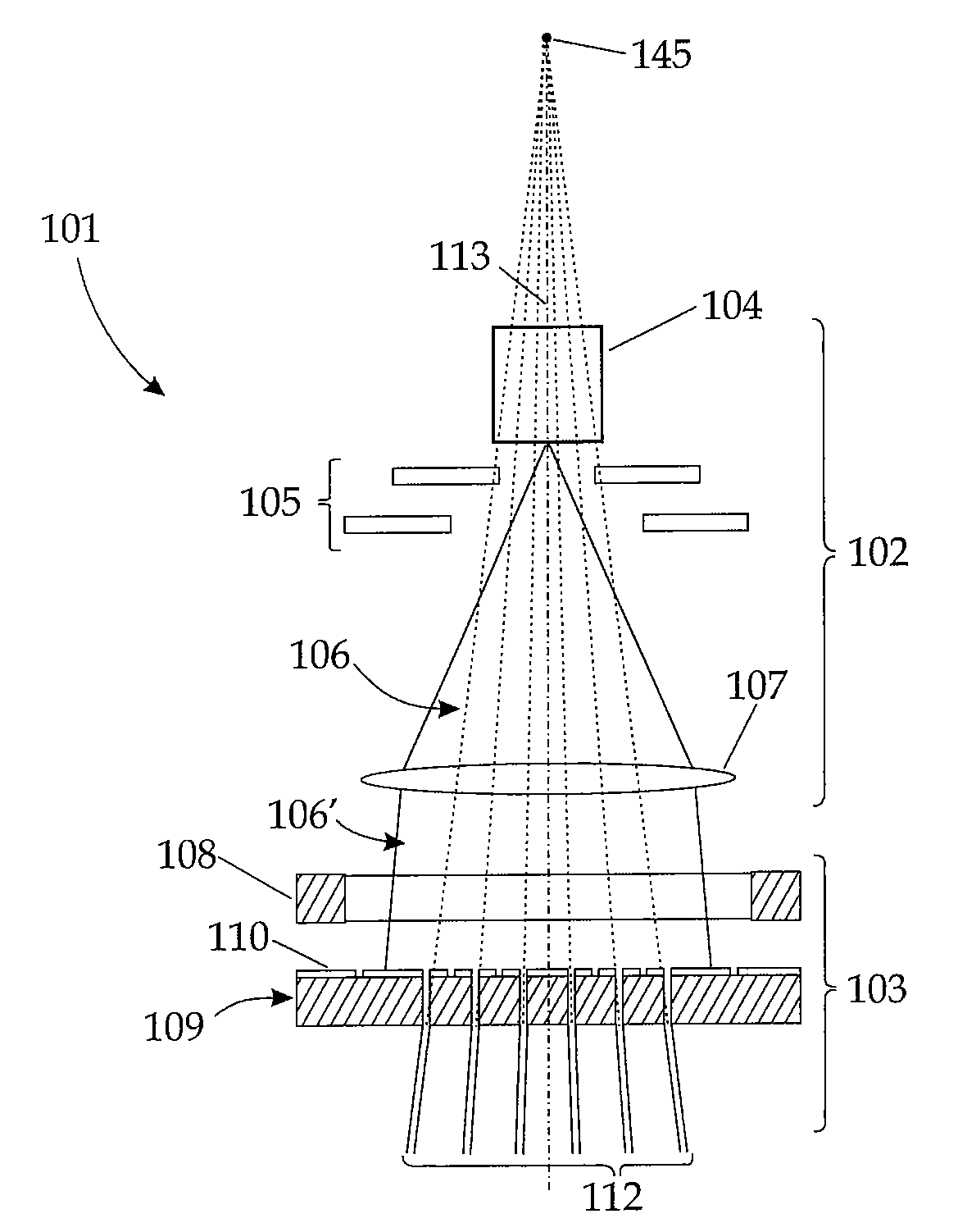
[0071]FIG. 1 shows a multi-beam source 101 according to the invention, comprising an illumination system 102 and a beam-forming system 103, arranged consecutively as seen in the direction of the particle beam, which propagates vertically downward in FIG. 1. The lateral dimensions of the figures are not to scale.

[0072]The illumination system 102 comprises a particle source 104 and an extractor lens array 105. Preferably, the electrically charged particles used in the multi-beam source are ions such as helium ions, but also heavier ions can be used. Protons or electrons can be used as well. The particles, emerging from the partic...


PUM


Abstract

A multi-beam source for generating a plurality of beamlets of energetic electrically charged particles. The multi-beam source includes an illumination system generating an illuminating beam of charged particles and a beam-forming system being arranged after the illumination system as seen in the direction of the beam, adapted to form a plurality of telecentric or homocentric beamlets out of the illuminating beam. The beam forming system includes a beam-splitter and an electrical zone device, the electrical zone having a composite electrode composed of a plurality of substantially planar partial electrodes, adapted to be applied different electrostatic potentials and thus influencing the beamlets.

Description

FIELD OF THE INVENTION AND DESCRIPTION OF PRIOR ART[0001]The invention relates to a multi-beam source for generating a plurality of beamlets of energetic charged particles, the multi-beam source comprising an illumination system and a beam forming system.[0002]Furthermore, the invention is related to an electrical zone plate for use in such a multi-beam source and an apparatus for multi-beam lithography for irradiating a target by means of a beam of energetic electrically charged particles, employing such a multi-beam source.BACKGROUND[0003]Multi-beam sources of the above mentioned kind can be used for a variety of applications, like lithography and microscopy systems. Some of the systems employing multi-beam sources use a single source generating one beam which is subsequently split into a plurality of beamlets. The charged particle sources used in such systems typically emit a charged particle beam with a defined opening angle, i.e. a diverging beam. The diverging beam often needs...

Claims


Application Information

Patent Timeline
Patent Type & Authority Patents(United States)
IPC IPC(8): A61N5/00G21G5/00
CPCB82Y10/00B82Y40/00H01J37/12H01J37/3007H01J37/3177H01J2237/0437H01J2237/0453H01J2237/04928H01J2237/1205H01J2237/1501H01J2237/151H01J2237/3045
Inventor PLATZGUMMER, ELMAR
Owner IMS NANOFABTION
Why Eureka
Try Eureka