Charged-Particle Exposure Apparatus With Electrostatic Zone Plate

Active Publication Date: 2008-09-25
IMS NANOFABTION
View PDF7 Cites 25 Cited by
  • Summary
  • Abstract
  • Description
  • Claims
  • Application Information

AI Technical Summary

Benefits of technology

[0008]It is one goal of the present invention to provide a particle-beam system using divergent lenses in order to reduce the various aberration effects present in the illumination and/or projections s

Problems solved by technology

A problem often encountered with electrooptical systems is the compensation of imaging aberrations and distortions.
For example, in the case of aberrations of the illuminating beam, a situation may arise where the passage of a beamlet is blocked since the local direction of the beamlet is not in line with the arrangement of consecutive openings in the plate co

Method used


Image

  • Charged-Particle Exposure Apparatus With Electrostatic Zone Plate
  • Charged-Particle Exposure Apparatus With Electrostatic Zone Plate
  • Charged-Particle Exposure Apparatus With Electrostatic Zone Plate

Examples


Embodiment Construction

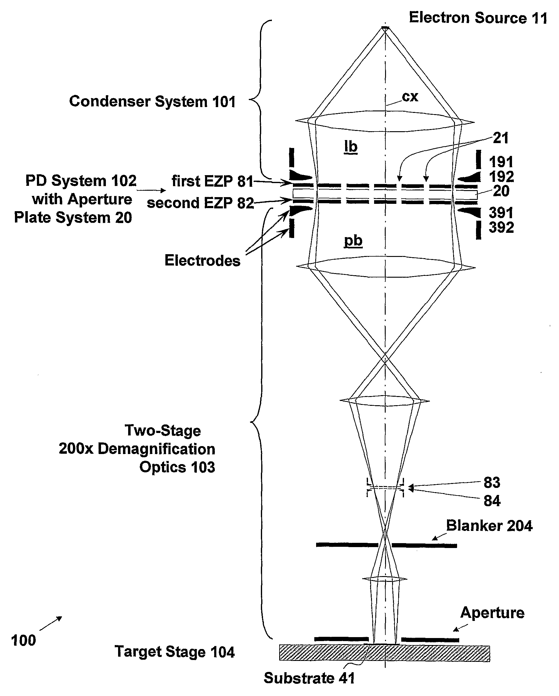
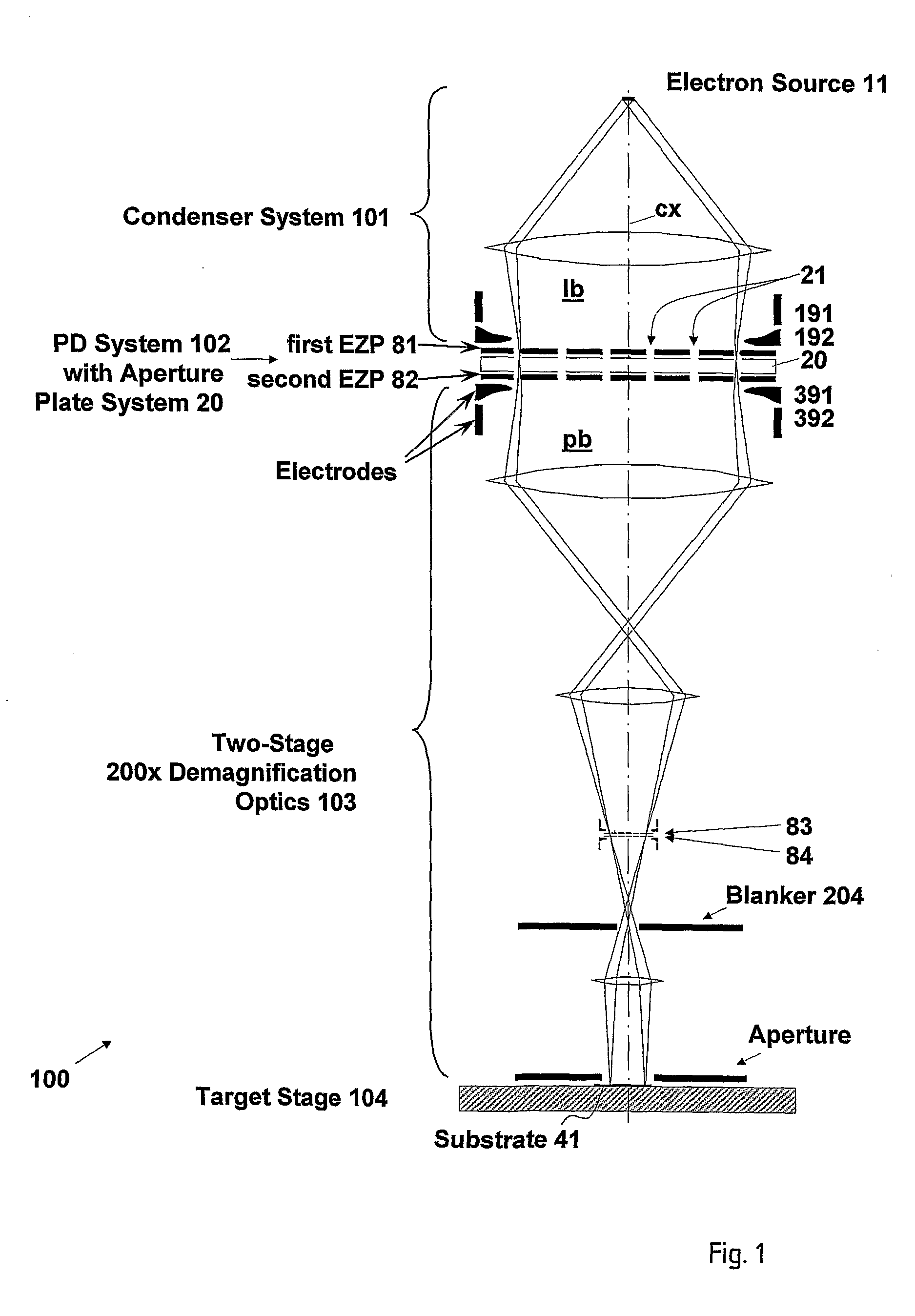
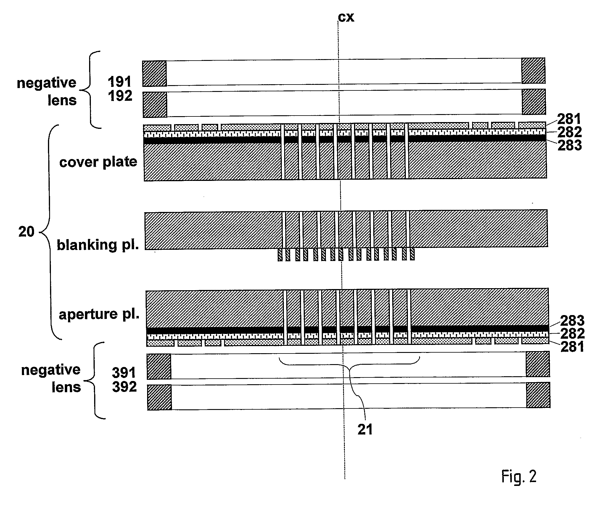
[0049]The present invention arranges for providing a particle-beam system using divergent lenses formed by tube electrodes (ring electrodes, annular electrodes) and a composite plate electrode. The composite plate electrode is, for instance, realized as a planar electrostatic zone plate (EZP) having a multitude of multi-zone electrodes. The EZP comprises holes for the passage of the particle beam through the apertures of the PD device and is arranged in the beam path, perpendicular to the optical axis. The system of tube electrodes and EZP can be integrated to the illuminating system and / or to the projection system. (Correspondingly, the EZP is immediately in front of or after the PD device, respectively.) It is important to note that in the framework of this disclosure, the term tube electrodes also includes multipole electrodes, for example octupoles, which have tubular or annular shape as a whole. In an advanced embodiment of the invention, the EZP can be integrated additionally ...


PUM


Abstract

In a particle-beam projection processing apparatus for irradiating a target by a beam of energetic electrically charged particles, including an illumination system, a pattern definition system for positioning an aperture arrangement composed of apertures transparent to the energetic particles in the path of the illuminating beam, and a projection system to project the beam onto a target, there is provided at least one plate electrode device, which has openings corresponding to the apertures of the pattern definition system and including a composite electrode composed of a number of partial electrodes being arranged non-overlapping and adjoining to each other, the total lateral dimensions of the composite electrode covering the aperture arrangement of the pattern definition system. The partial electrodes can be applied different electrostatic potentials.

Description

FIELD OF THE INVENTION AND DESCRIPTION OF PRIOR ART[0001]The invention relates to improvements on particle-beam projection processing apparatus for irradiating a target by means of a beam of energetic electrically charged particles, comprising an illumination system, a pattern definition (PD) system and a projection system in order to project the beam patterned by the PD system onto a target positioned after the projection system. The illumination system serves to generate and form the energetic particles into a wide-area illuminating beam which is substantially tele / homocentric at the location of the PD system and sufficiently wide to illuminate the entire area reserved for apertures in the PD system simultaneously; the PD system, located after the illumination system as seen along the direction of the beam, positions an aperture arrangement composed of apertures transparent to the energetic particles in the path of the illuminating beam, thus forming a patterned beam emerging from...

Claims


Application Information

Patent Timeline
IPC IPC(8): H01J3/14G21K5/00
CPCB82Y10/00H01J37/3174B82Y40/00
Inventor PLATZGUMMER, ELMARCEMUSCA, STEFAN
Owner IMS NANOFABTION
Why Eureka
Try Eureka