
Method for in-progress telephone call transfer between a wireless telephone and a wired telephone using a short-range communication control link

a control link and in-progress telephone technology, applied in the field of telecommunications, can solve the problems of complex control circuit and dedicated communication channels, poor link quality, and inability to transfer in-progress telephone calls, so as to avoid the use of complex interface circuits, simple and easy to implement and use

Inactive Publication Date: 2006-02-14
KONINKLIJKE PHILIPS ELECTRONICS NV
View PDF12 Cites 51 Cited by
  • Summary
  • Abstract
  • Description
  • Claims
  • Application Information

AI Technical Summary

Benefits of technology

[0009]By using the short-range wireless communication link to exchange the telephone number data, the present invention avoids the use of complex interface circuitry, and it much simpler and easier to implement and use as compared to the prior art. As long as the wireless and wired telephones are provisioned with the short-range wireless transceiver and can communicate using the given protocol, in-progress call transfer between the devices is reliable and secure.

Problems solved by technology

Nevertheless, those who use cellular telephones often find themselves cut off or dropped in the middle of a wireless call for any number of reasons, such as battery loss, network connection problems, or the like.
Even when the connection between the cellular telephone and the wireless network remains intact, the link quality may be very poor, for example, as the user moves between cells.
Although the technique described in the Jensen et al. patent provides for in-progress call transfer between wireless and wired telephone devices, it requires a complex control circuit and dedicated communication channels.

Method used


Image

  • Method for in-progress telephone call transfer between a wireless telephone and a wired telephone using a short-range communication control link
  • Method for in-progress telephone call transfer between a wireless telephone and a wired telephone using a short-range communication control link
  • Method for in-progress telephone call transfer between a wireless telephone and a wired telephone using a short-range communication control link

Examples


Embodiment Construction

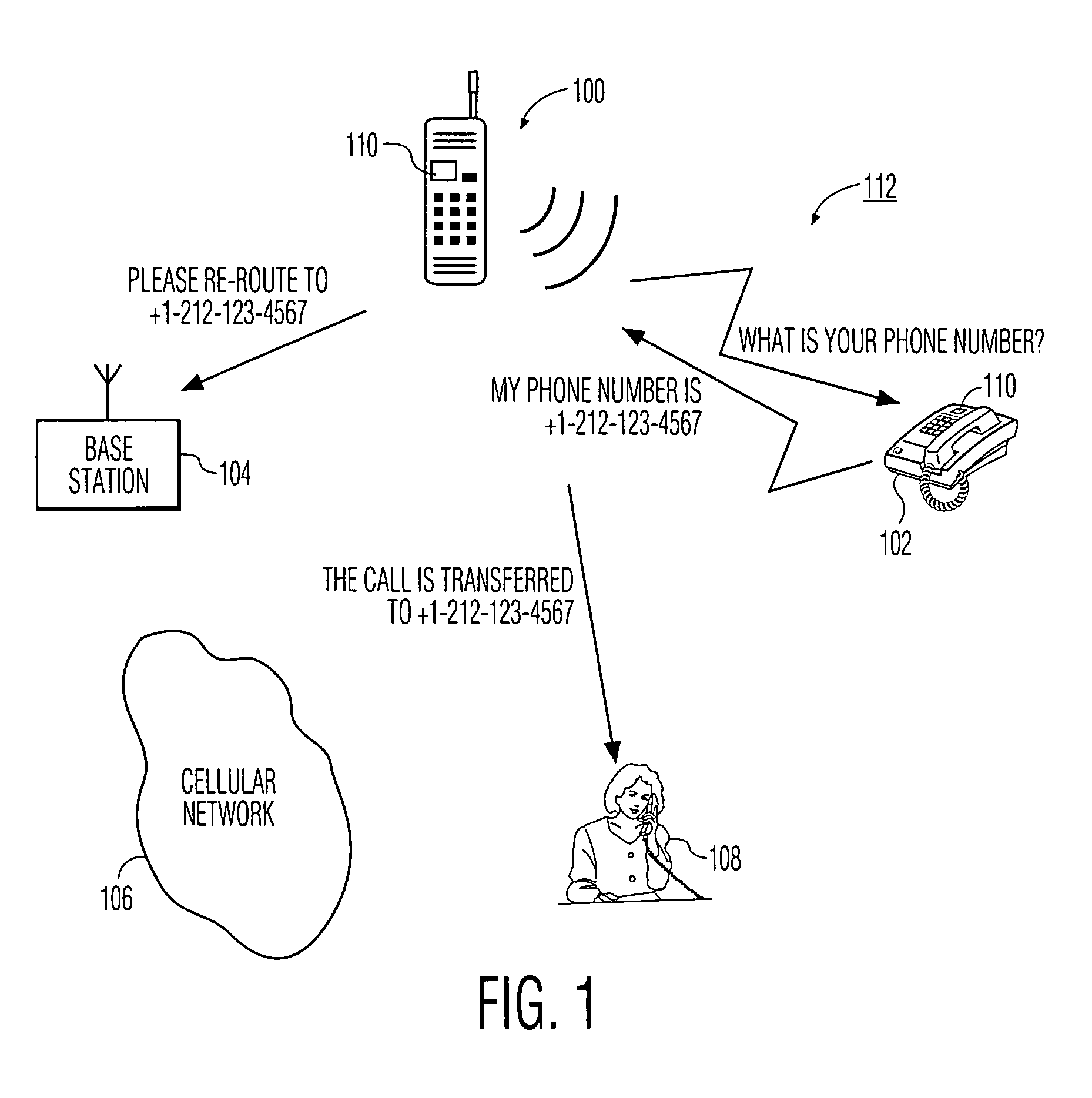
[0018]FIG. 1 is a simplified illustration of how an in-progress telephone call is transferred between a wireless telephone device 100 and a wired or “wireline” telephone device 102 according to the present invention. The wireless telephone device is sometimes referred to herein as a mobile radio handset or a cellular telephone. As illustrated in this drawing, the wireless telephone is connected to a base station 104, which is part of a cellular telephone network 106. The wired telephone device 102 is connected to a wireline telephone network 108 in the usual manner. Further details concerning this known telephone system architecture are provided below.

[0019]Each telephone device includes a similar short-range wireless transceiver 110 to enable the devices to communicate with each other over a short-range wireless communication link 112. Preferably, the devices communicate using a given short-range radio link that conforms to a given protocol. In a particularly preferred embodiment, ...


PUM


Abstract

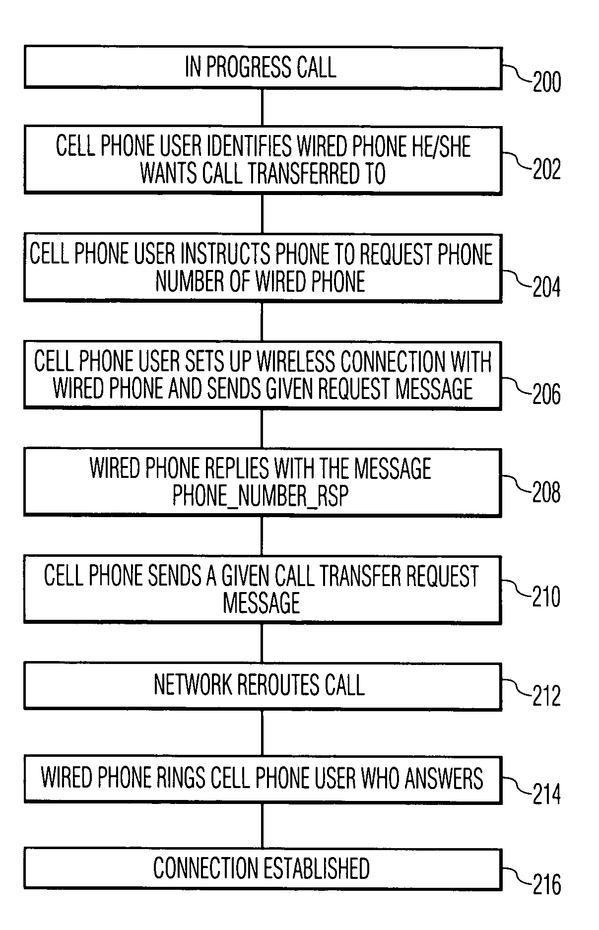
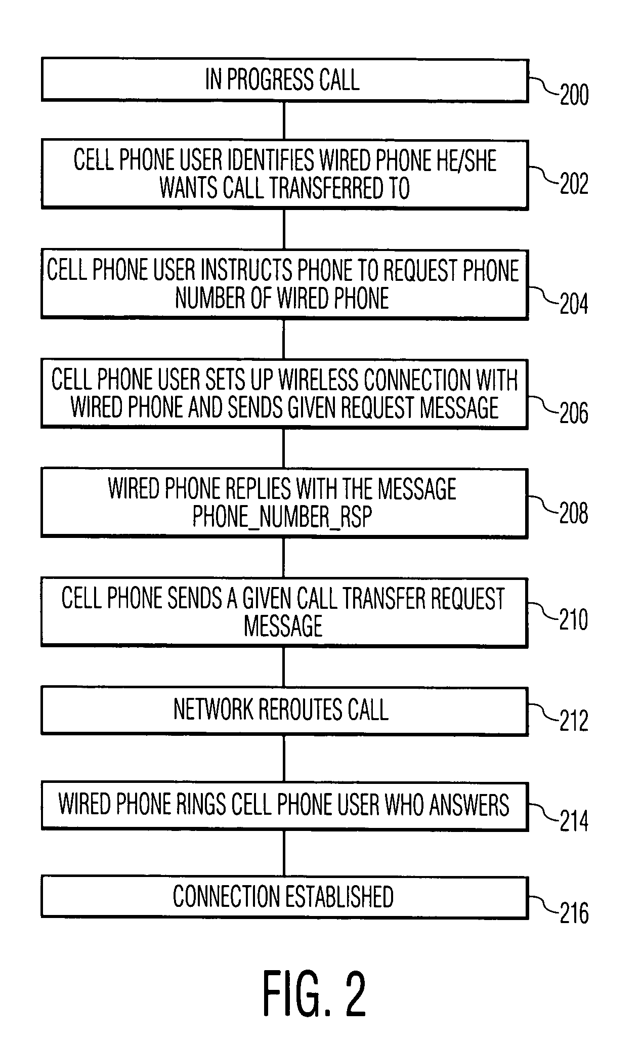
In-progress call transfer between a wireless telephone and a wired telephone is effected using a short-range wireless communication link between the devices. Each of the devices are provisioned to include a short-range radio or infrared transceiver so that the devices can communicate with each other over the short-range wireless communication link, preferably using a given short-range wireless protocol. When the wireless telephone's battery is almost exhausted, or for any other reason that the user may desire, the wireless telephone requests the wired telephone's phone number by communicating with wired telephone over the short-range wireless communication link. Upon receipt of the wired telephone's phone number the wireless telephone issues a call transfer request to a cellular base station, passing the wired telephone's phone number. The base station and the network then re-route the call to the wired telephone.

Description

BACKGROUND OF THE INVENTION[0001]1. Technical Field[0002]The present invention relates generally to telecommunications and, in particular, to a method for transferring an in-progress telephone call between wireless and wired telephones operating in proximity to each other.[0003]2. Description of the Related Art[0004]Low-priced, state-of-the art cellular telephones are now widely available in the consumer marketplace. Indeed, many individuals now use cellular communications for much of their business as well as personal use. Nevertheless, those who use cellular telephones often find themselves cut off or dropped in the middle of a wireless call for any number of reasons, such as battery loss, network connection problems, or the like. Even when the connection between the cellular telephone and the wireless network remains intact, the link quality may be very poor, for example, as the user moves between cells. For these and other reasons, there has developed a need in the art to provid...

Claims


Application Information

Patent Timeline
IPC IPC(8): H04Q7/20H04M1/00H04M1/724H04M3/58H04M7/12H04W4/16H04W76/04H04W88/06H04W92/18
CPCH04M1/006H04M1/72519H04M3/58H04W76/04H04M7/12H04M2207/18H04W92/18H04M2250/02H04W4/16H04W76/023H04W88/06H04M2207/20H04W76/14H04W76/20H04M1/724
Inventor HENON, ALEXANDRE
Owner KONINKLIJKE PHILIPS ELECTRONICS NV
Learn More