Locker system, locker controlling method, control center, and recording medium

a locker and control method technology, applied in the field of locker systems, can solve the problems of inconvenient use, inability to know which locker is which, and incompatible with sharing the compartment among some users, and achieve the effect of convenient handling

Inactive Publication Date: 2006-02-14
NEC CORP
View PDF39 Cites 68 Cited by
  • Summary
  • Abstract
  • Description
  • Claims
  • Application Information

AI Technical Summary

Benefits of technology

[0012]The present invention has been made in consideration of the above problems. It is an object of the present invention to realize a secure locker system with easy handling.
[0029]the control center may transmit an instruction to the locker controllers so as to keep unused locker compartments being locked.
[0042]According to the above locker system, the deliverer and the recipient can share the locker. It is helpful for establishing more convenient delivery support system.
[0043]Moreover, in a case where advertisement function is given to the lockers, it is able to provide personalized advertisement while the user is using the locker. It improves efficiency of the advertisement.

Problems solved by technology

The user must bring some coins when using the locker, and the business managing the lockers has a troublesome task to collect the coins from every locker.
The conventional coin-operated locker has such the inconvenient matters both for users and business, because it is coin-operated.
Moreover, users have no ways to know which locker is available beforehand.
Furthermore, since one key is paired with one locker compartment, it is not compatible with sharing the compartment among some users.
However, since users of the lockers are unknown, this method is not suitable for personalized advertisement.
However, the key must be passed to the recipient from the deliverer, therefore, it is still troublesome.
Since the system requires registration of user information and issuance of the ID card, it brings troublesome tasks to the user data management section, etc.
Therefore, establishment of the system costs much.
Moreover, the system is inappropriate for public use, because the locker is unavailable for unregistered persons who do not have the ID card.

Method used


Image

  • Locker system, locker controlling method, control center, and recording medium
  • Locker system, locker controlling method, control center, and recording medium
  • Locker system, locker controlling method, control center, and recording medium

Examples


first embodiment

[0131]An embodiment of the present invention will now be described with reference to accompanying drawings.

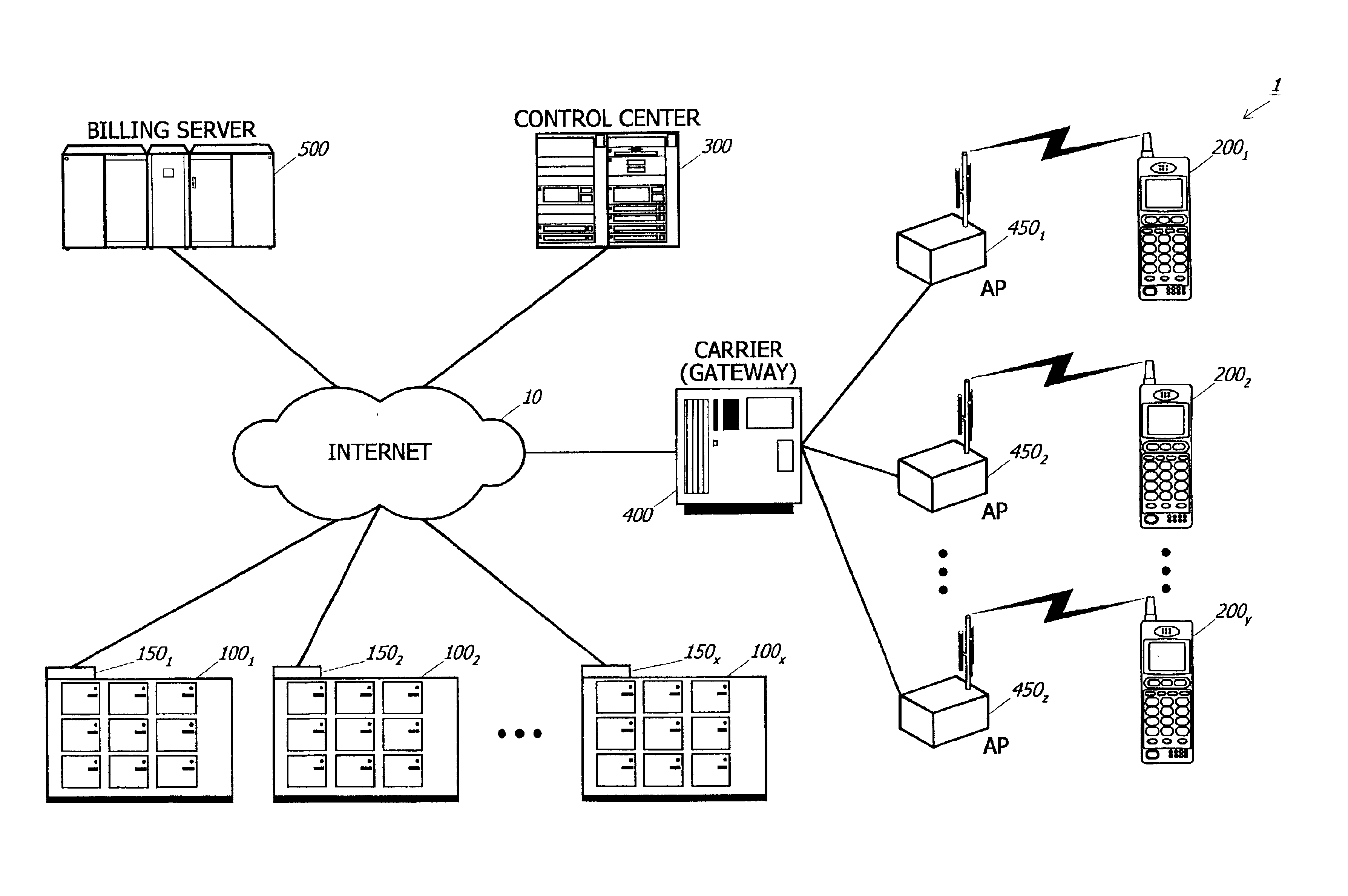
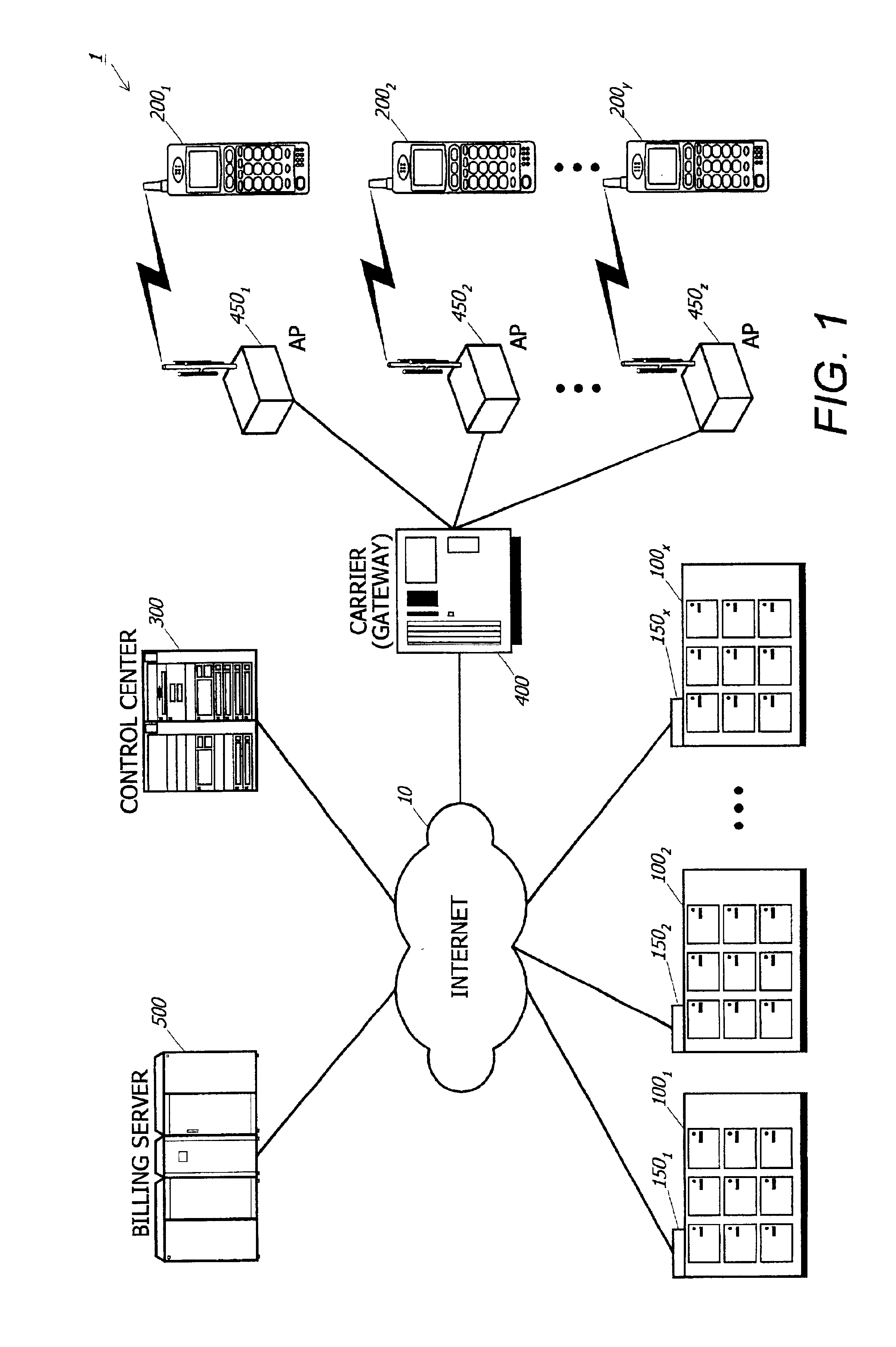
[0132]FIG. 1 is a diagram schematically showing a locker system according to a first embodiment. As shown in FIG. 1, the locker system 1 comprises a telecommunications network (Internet) 10, a plurality of locker units 1001 to 100x to which locker controllers 1501-150x are applied respectively, a plurality of user terminals 2001-200y, a control center 300, a gateway (carrier) 400 being connected to access points (AP) 4501-450z, and a billing server 500.

[0133]The telecommunication network 10 interconnects the locker controllers 150, the control center 300, the gateway 400, and the billing server 500. The telecommunications network 10 may be the Internet which is based on predetermined communication protocols such as TCP / IP (Transmission Control Protocol / Internet Protocol). In these embodiments, the Internet will be employed as the telecommunications network 10 (hereinafter, refe...

second embodiment

[0201]The first embodiment raises an example of a service for a single user. The present invention also realizes a service for sharing one locker box among a plurality of users. An example of the locker sharing will now be described as a second embodiment. Structural feature of the second embodiment is basically the same as that of the first embodiment.

[0202]In this embodiment, a case where a user A drops the baggage in the locker box and another user B retrieves it will be explained.

[0203]The user A operates the user terminal 200 to search the available locker box and reserves the found available locker. Those processes are the same as the locker search process (FIG. 7) and the locker reserve process (FIG. 11) according to the first embodiment.

[0204]After the reservation has been done, the user A transmits an unlock request to the control center 300 as well as the first embodiment, thus the specified locker box is unlocked and the user A drops the baggage therein.

[0205]Then, the us...

third embodiment

[0212]The locker system according to the present invention may be applicable to the delivery service. An example where the locker system is applied to the delivery service will now be described as a third embodiment.

[0213]FIG. 18 is a diagram showing the locker system 2 according to the third embodiment. Structural features of the locker system 2 are basically the same as those of the locker system 1 according to the first and second embodiments, therefore, the same reference symbols denote the same components. In addition to the structure of the locker system 1, the locker system 2 comprises a delivery service center 600 and deliverer terminals 700.

[0214]The delivery service center 600 may comprise a main frame, a workstation or the like which is accessible to the Internet 10. The delivery service center 600 may be operated by a delivery service business which has contracted with the locker management business to use the locker units 100 for the delivery service. In this embodiment...


PUM


Abstract

A user access the control center by a user terminal, and send a request for searching an available locker box in a desired area. The control center has database storing data representing which locker box is available. The control center searches the database for the available locker box which matches the user's request. The control center transmits information of the available locker to the user terminal. As the user reserves the locker, the control center generates one time password (OTP). The control center sends the OTP to the locker controller, and a display unit of the locker displays the OTP. The user inputs the displayed OTP to the user terminal and sends it to the control center. If the OTP is successfully authenticated, the control center sends commands to unlock the locker, thus, the user can use the reserved locker box.

Description

BACKGROUND OF THE INVENTION[0001]1. Field of the Invention[0002]The present invention relates to a locker system, a locker controlling method, a control center, and a recording medium, for remotely controlling lockers.[0003]2. Description of the Related Art[0004]A coin-operated locker has been known as a public-use locker which keeps baggage for a while. Such the conventional coin-operated locker employs a manually operated lock system which is operated by a user after coin insertion.[0005]The user must bring some coins when using the locker, and the business managing the lockers has a troublesome task to collect the coins from every locker. The conventional coin-operated locker has such the inconvenient matters both for users and business, because it is coin-operated.[0006]Moreover, users have no ways to know which locker is available beforehand. Therefore, they sometimes must walk around to looking for available locker if the nearest lockers are fully used.[0007]Because of the man...

Claims


Application Information

Patent Timeline
Patent Type & Authority Patents(United States)
IPC IPC(8): G06F19/00G07F7/00G07F17/12
CPCG07F17/0014G07F17/12G06Q50/10G07F17/13
Inventor INOMATA, YOSHIHIRO
Owner NEC CORP
Why Eureka
Try Eureka