Eureka AIR delivers breakthrough ideas for toughest innovation challenges, trusted by R&D personnel around the world.

Method and apparatus for change data capture in a database system

a database system and change data technology, applied in the field of database systems, can solve the problems of cumbersome loading mechanism, cumbersome data extraction, cumbersome conventional data extraction, transport, etc., and achieve the effect of complicating the task

Inactive Publication Date: 2006-02-14
ORACLE INT CORP
View PDF12 Cites 57 Cited by
  • Summary
  • Abstract
  • Description
  • Claims
  • Application Information

AI Technical Summary

Benefits of technology

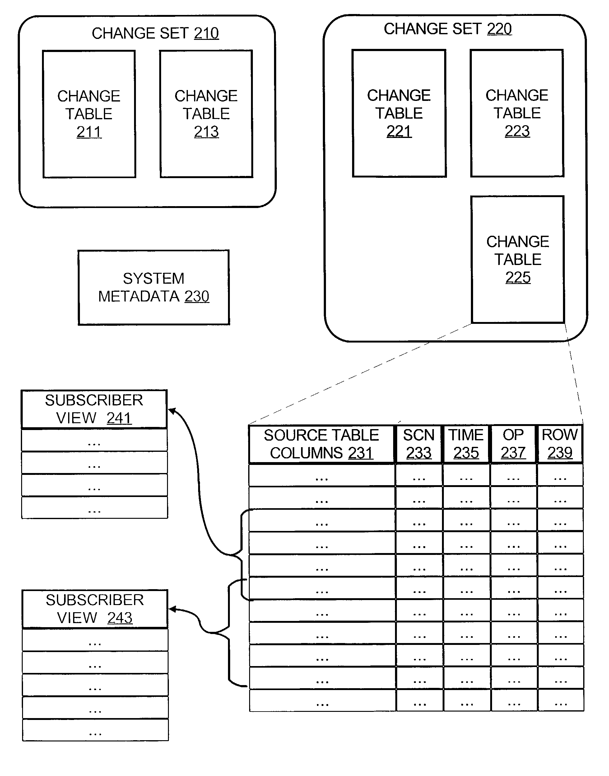
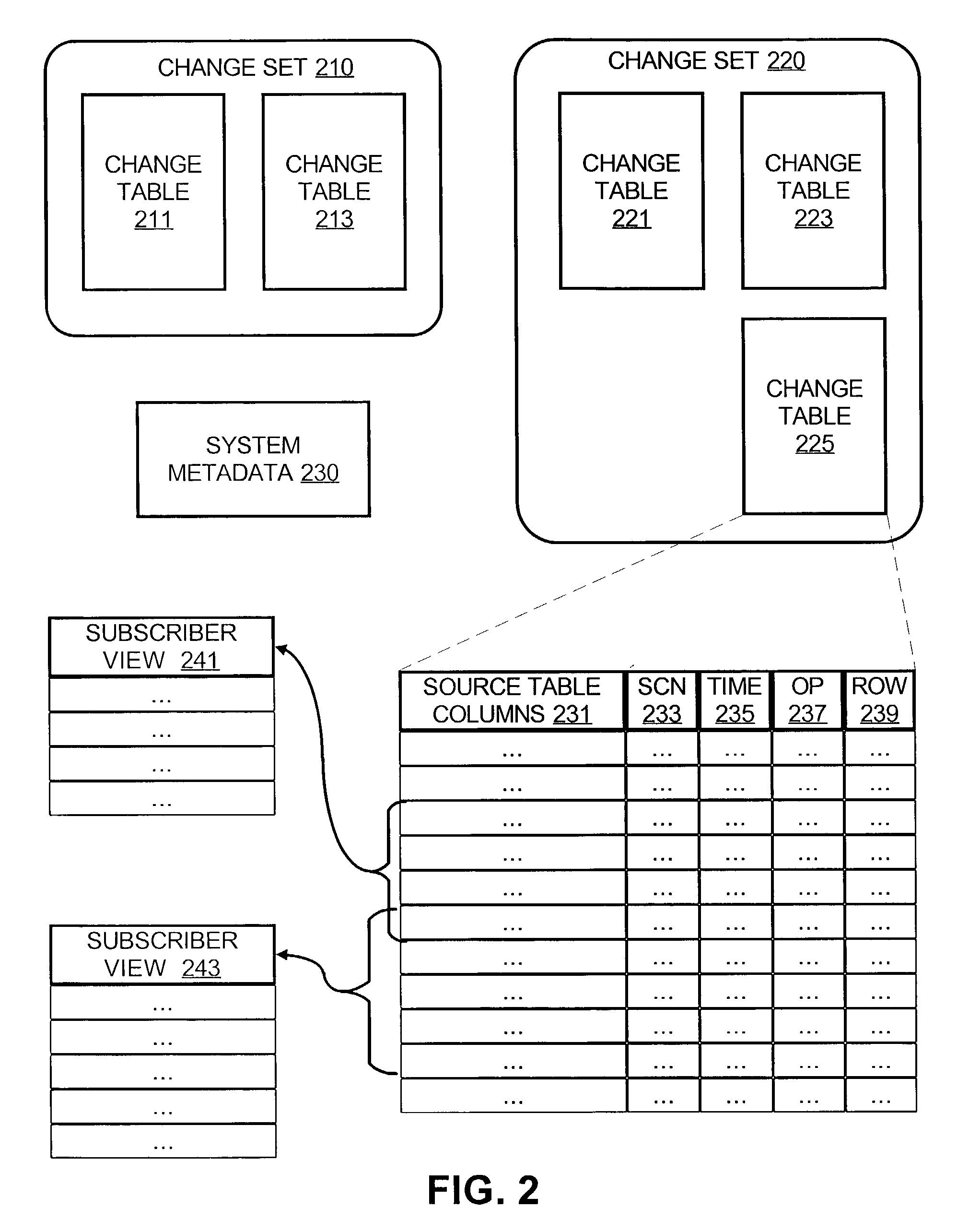
[0012]The present invention addresses these and other needs by capturing modifications made to OLTP tables (e.g. inserts, updates, and deletes) in a database object, referred to as a change table. The change data in the change table is then made available to analysis applications in a controlled manner, for example, in accordance with a publication-subscription model, to prevent loss or double counting of the change data.
[0014]Subscription includes a mechanism for an analysis application to request access to the change data in the change tables in a manner such that the change data is retrieved with no data loss or double counting. Specifically, change data is only deleted from the change tables when all of the subscriber applications indicate that the change data is no longer needed (e.g. because the change data has been processed). Furthermore, double counting is avoided by only providing new change data to a subscriber in response to a request for new change data. Thus a subscriber is capable of rereading the same rows of the change table as often as needed without regard to the new changes that are being captured and loaded into the change table.

Problems solved by technology

Aggregating and analyzing this data, however, is computationally expensive and, if performed on the OLTP system itself, would decrease the performance of the OLTP system.
Conventional data extraction, transport, and loading mechanisms are cumbersome.
In this approach, the amount of data extracted, transported, and loaded is as immense as the amount of data in the OLTP system, even though only a small percentage of the data on the OLTP system is actually new.
Not only is this schema change an administrative nightmare, many vendors of OLTP systems forbid their customers from making any changes to the schema for security, maintenance, and liability reasons.
Second, there is a performance hit in storing the timestamp for every row of new or changed data, yet performance is critical for OLTP systems.
Third, while timestamps can easily identify which rows have changed due to an insert or update, timestamps cannot distinguish between a newly inserted row or an old row that was updated.
Furthermore, timestamps cannot identify deleted rows, because deleted rows are no longer present in the database.
The lack of this kind of change information makes it difficult to properly update summaries of the OLTP data, resulting in expensive recalculations of the summary data.
The conventional flat file approach is also disadvantageous for data transport.
Thus, flat files cannot take advantage of the sophisticated file management functions provided by modern database management systems, such as crash recovery for robust data protection and data partitioning and indexing for efficient data processing.
Consequently, storing the changed data in flat files increases the risk that data will be lost or corrupted and greatly complicates the task of joining or combining the changed data with the data that is stored in the data warehouse for use by the data analysis applications.
In terms of data loading, the conventional flat file approach also suffers from data loss and double counting.
When the flat file grows too large for the data warehouse system, the system administrator is likely to delete the oldest data in the flat file arbitrarily.
If a data analysis application has not yet processed the deleted data, that data is permanently lost to the application, resulting in inaccurate summaries of the OLTP data.
On the other hand, if the data analysis application needs to make multiple passes on the flat file to process the data, the data analysis application cannot identify the data that has been newly added to the flat file.
Typically, the data analysis application is forced to reprocess all the data in the flat file, resulting in double counting of the old data.

Method used


Image

  • Method and apparatus for change data capture in a database system
  • Method and apparatus for change data capture in a database system
  • Method and apparatus for change data capture in a database system

Examples


working example

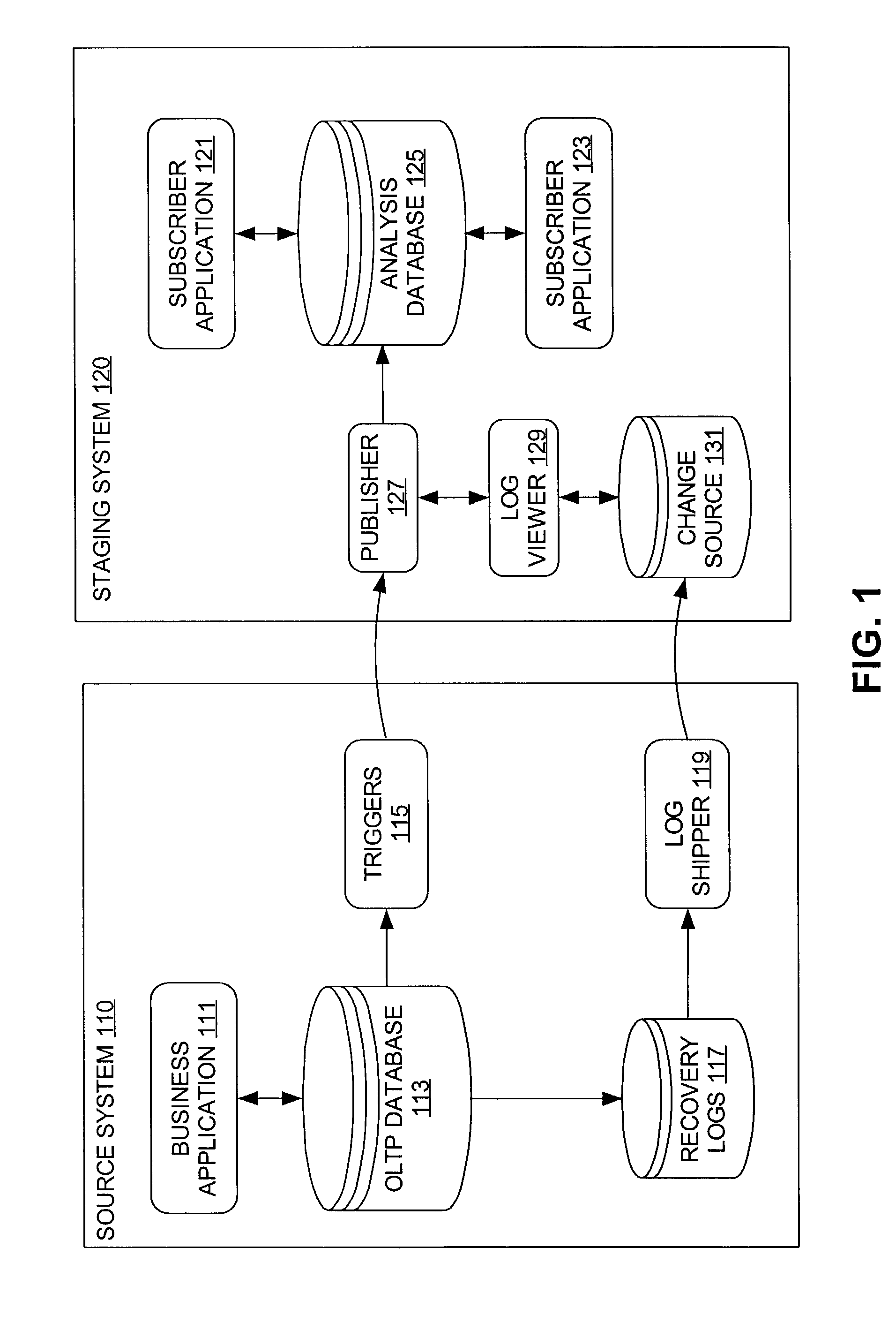
[0052]FIGS. 5A, 5B, 5C, 5D, 5E, and 5F show a sequence of phases of a working example that illustrates how one embodiment of the publication-subscription model operates. In FIG. 5A, a change table 500 contains four rows 501, 502, 503, 504 of change data. A first subscriber application 121 activates a subscription to change table 500 (step 401), extends the subscription window to the present (step 403), and obtains a subscriber view 510 (step 405). Accordingly, the first subscriber application 121 is able to process the four rows 501, 502, 503, 504 (step 407).

[0053]Next, in FIG. 5B, additional change data, comprising rows 505, 506, arrives and is added to the change table 500 (step 307). Because the first subscriber application 121 is currently working with the subscriber 510 based on its subscription window, the first subscriber application 121 does not see the additional change data 505, 506 in the change table 500. Thus, the first subscriber application 121 is free to make as many...


PUM


Abstract

A method of change data captured is disclosed, in which modifications made to on-line transaction processing (OLTP) tables (e.g. inserts, updates, and deletes) are maintained in a database object, referred to as a change table. The change data in the change table is then made available to analysis applications in a controlled manner, such as in accordance with a publication-subscription model.

Description

RELATED APPLICATIONS[0001]The present application is related to U.S. patent application Ser. No. 09 / 863,419 entitled “Asynchronous Change Capture for Data Warehousing” filed on May 24, 2001 by William D. Norcott, the contents of which are hereby incorporated by reference.[0002]The present application is related to U.S. patent application Ser. No. 09 / 863,422 entitled “Synchronous Change Data Capture in a Relational Database” filed on May 24, 2001 by William D. Norcott, the contents of which are hereby incorporated by reference.FIELD OF THE INVENTION[0003]The present invention relates to database systems and more particularly to a method and apparatus for change data capture in a database system.BACKGROUND OF THE INVENTION[0004]Many businesses and other large organizations today use relational database management systems to execute and keep track of business transactions. These systems are known as on-line transaction processing (OLTP) systems. For example, a company that sells produc...

Claims


Application Information

Patent Timeline
Patent Type & Authority Patents(United States)
IPC IPC(8): G06F17/30G06F12/00
CPCG06F17/30368G06F17/30563Y10S707/99954Y10S707/99943G06F16/2358G06F16/254
Inventor NORCOTT, WILLIAM D.BREY, MICHAELGALANES, JOHNBINGHAM, PAULAGUZMAN, RAYMOND
Owner ORACLE INT CORP
Why Eureka
Eureka Blog
Learn More