
Gravity hinge

a gravity hinge and hinge technology, applied in the field of hinge closures, can solve the problems of frequent maintenance, premature failure of the hinge without some form of external lubrication, and polymer cams are far more susceptible to torsional failures than metallic cams, and achieve the effects of reducing or eliminating electrical conduction, and being convenient to maintain

Inactive Publication Date: 2006-02-21
POLY TECH INDAL
View PDF30 Cites 44 Cited by
  • Summary
  • Abstract
  • Description
  • Claims
  • Application Information

AI Technical Summary

Benefits of technology

[0009]A further object of the invention is to provide a gravity hinge that is efficiently designed and easy to maintain.
[0010]A still further object of the invention is to provide a gravity hinge that eliminates the need for periodic lubrication of the hinge joint.
[0011]A still further object of the invention is to provide a gravity hinge, gate and fencing system that reduces or eliminates electrical conduction between the fence portion and the gate portion of the system.

Problems solved by technology

One problem associated with known gravity gates is common to all devices that employ moving parts: friction.
In many instances the rotating portions of the hinges are in direct contact with one another which causes friction.
If the portions are made of metal, as they often are, the friction could lead to premature failure of the hinge absent some form of external lubrication.
External lubrication, most often in the form of grease, is messy and transitory thereby leading to frequent maintenance.
Although polymer cams reduce friction, polymer cams are far more susceptible to torsional failures than metallic cams.
Furthermore, the devices of these patents utilize multiple polymeric parts which increases the likelihood of torsional failure.
When these weaknesses are combined with the difficulties relating to machining and molding such intricate polymer parts, the impracticality of these hinges is readily apparent.
Another weakness of known hinge and gate designs is the free conduction of electricity.
Such conduction can be fatal.
For example, a hot wire falling on a metal railing could electrocute someone passing through a swing gate attached to the railing.

Method used


Image

  • Gravity hinge
  • Gravity hinge
  • Gravity hinge

Examples


Embodiment Construction

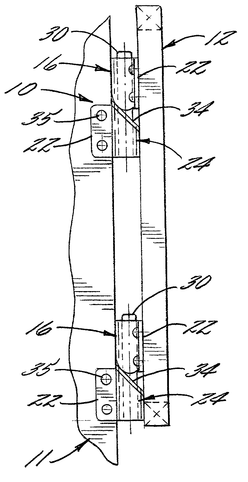
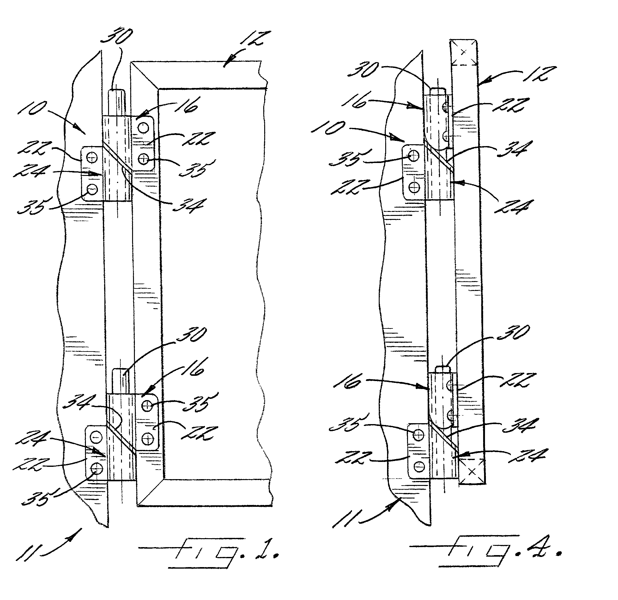
[0021]The invention provides a gravity hinge for use with a gate, door or other hinged closure. As used herein, the term “hinge” has its usual definition; e.g., “a jointed or flexible device on which a door, lid or other swinging part turns.” Merriam-Websters' Collegiate Dictionary (online edition, cited as of Jan. 9, 2001). Referring now to FIG. 1, there is shown a hinge 10 in accordance with the invention. For ease of discussion and presentation to the reader, the hinge 10 is shown in conjunction with a gate or door 12 and support post 14 such as would be commonly found in the practice of the invention. This particular setting, however, should not be interpreted as limiting in any way the scope of the invention.

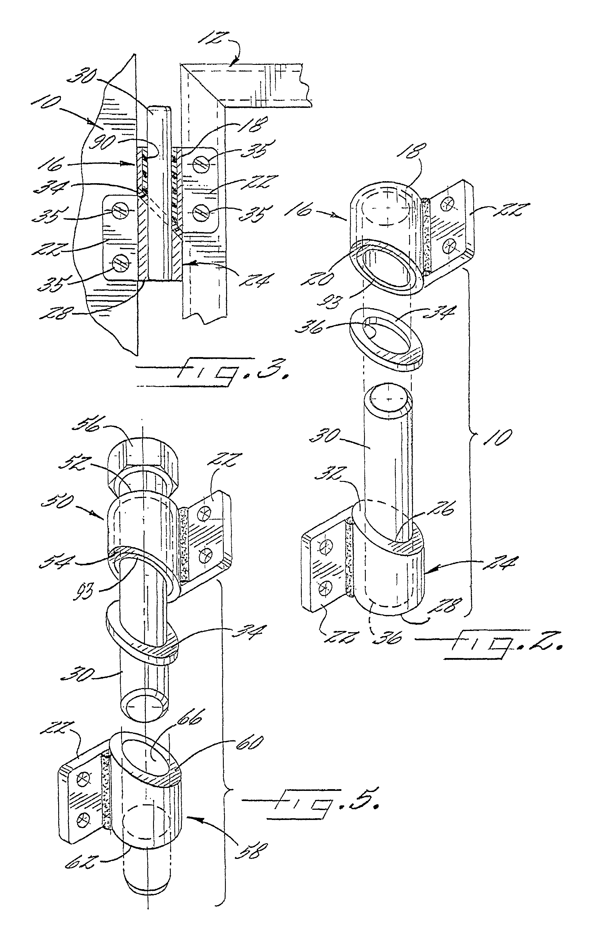
[0022]Referring now to FIG. 2, in a preferred embodiment the hinge 10 according to the invention comprises an upper tubular cylindrical knuckle 16. As used herein relational terms such as upper and lower are used for explanatory purposes and as an aid to the reader's interp...


PUM


Abstract

A gravity hinge is disclosed that is simple to manufacture and avoids limitations found in known gravity hinges. The hinge includes two cylindrical knuckles joined by a spindle and separated by a polymer bushing. The junction of the knuckles and the bushing is at an angle oblique to the vertical axis of the knuckles and spindle. The oblique angle causes the upper knuckle to rotate upward upon the application of a rotational force thereby storing potential energy. Upon the release of the rotational force the upper knuckle falls or (rotates) back into place thereby returning the hinge to its natural, closed position.

Description

FIELD OF THE INVENTION[0001]The invention relates to the field of closures; specifically hinge closures. In particular the invention relates to safety structures that incorporate hinges that operate primarily under the influence of gravity to secure closure of safety fences and gates.BACKGROUND OF THE INVENTION[0002]The present invention relates to safety barriers, and in particular relates to safety fences and gates in which opened gates return automatically to a closed position. One particular use for hinges along this line is pedestrian traffic control in industrial work areas. For example, Federal regulatory authorities (e.g., OSHA and EPA) require extensive systems to control the path and flow of workers in industrial plants. Hinged gates and doors are often used to restrict movement in areas deemed dangerous or to seal off areas containing harmful materials. Typically these regulations are implemented by installing extensive railing systems painted in fluorescent colors, usual...

Claims


Application Information

Patent Timeline
IPC IPC(8): E05F1/02E05D11/08E05F1/06
CPCE05F1/063Y10T16/53987Y10T16/53988Y10T16/539Y10T16/537
Inventor CEDRONE, DANIEL POMPEL
Owner POLY TECH INDAL
Features
  • Generate Ideas
  • Intellectual Property
  • Life Sciences
  • Materials
  • Tech Scout
  • Unparalleled Data Quality
  • Higher Quality Content
  • 60% Fewer Hallucinations
Learn More