Vacuum pipette for gripping electrical components by suction
- Summary
- Abstract
- Description
- Claims
- Application Information
AI Technical Summary
Benefits of technology
Problems solved by technology
Method used
Image
Examples
Embodiment Construction
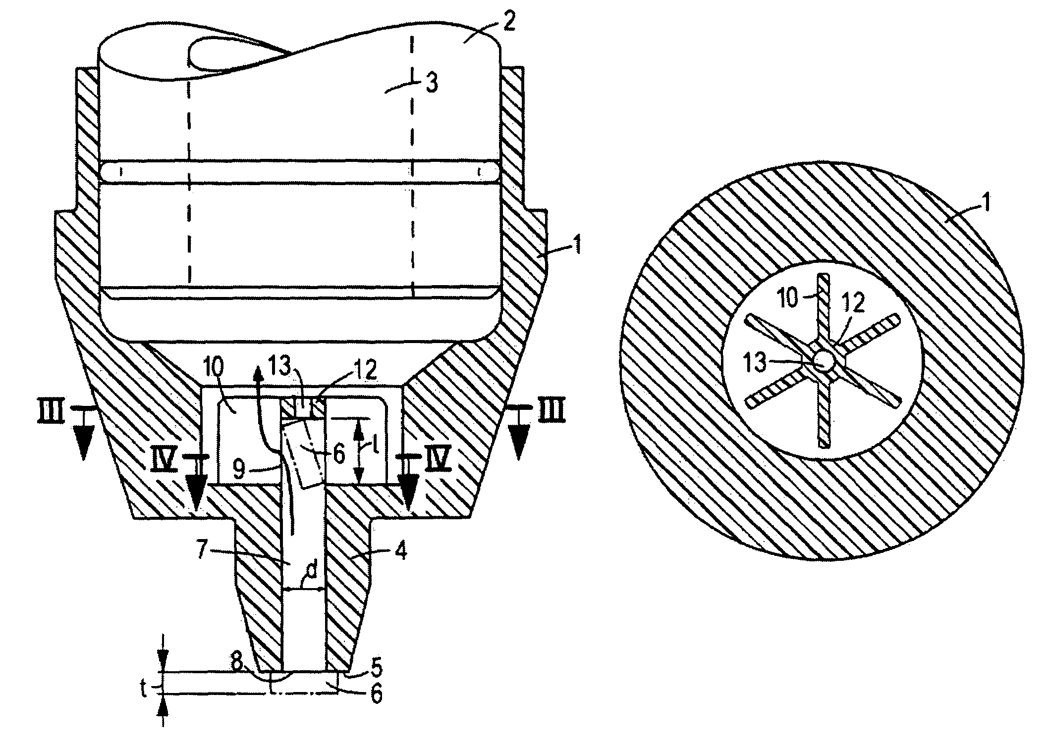
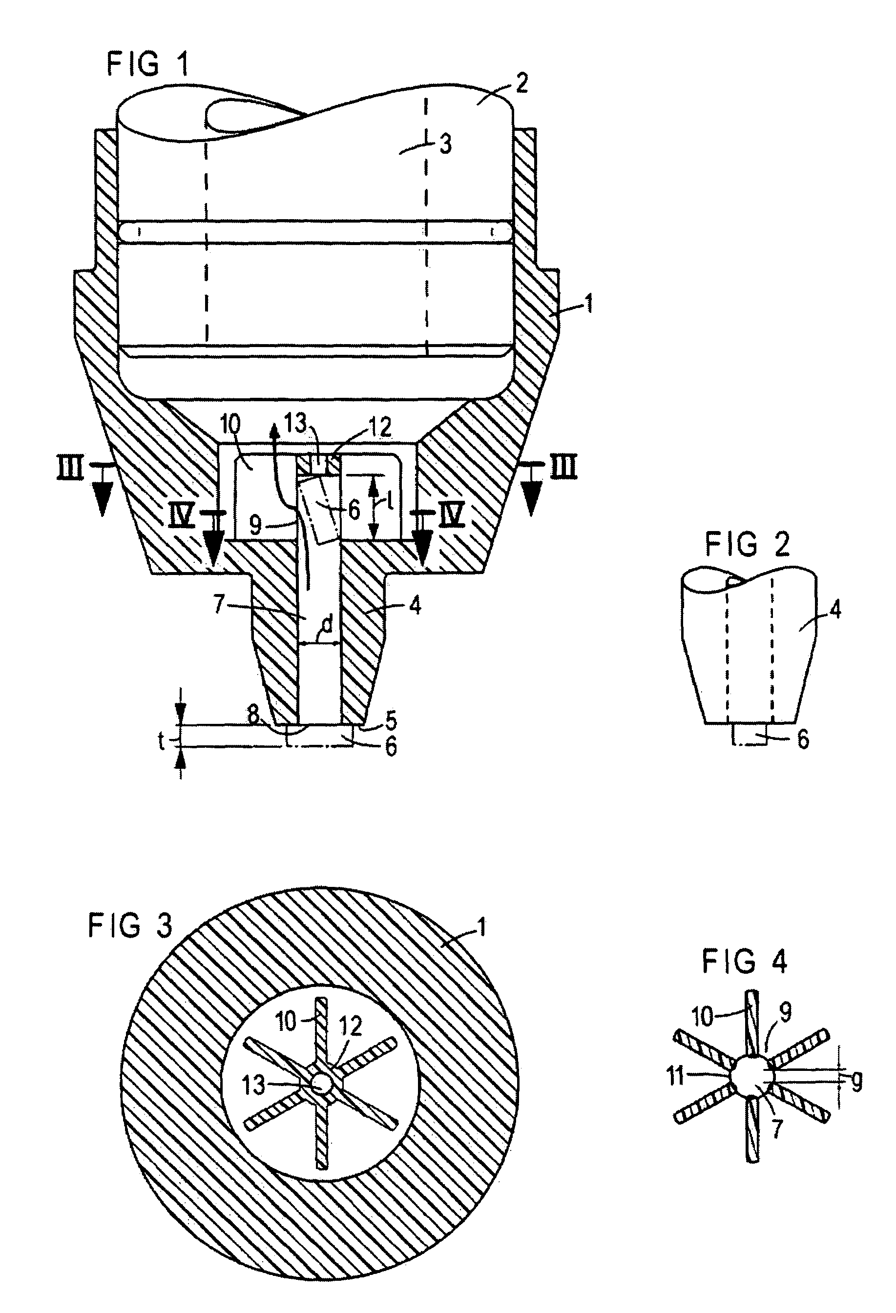
[0025]According to FIG. 1, a vacuum pipette 1 is mounted onto the end of a cylindrical shaft 2 of a placement head. The shaft 2 has a vacuum line 3 to which a vacuum, atmosphere or compressed air can be applied in a controllable manner using pneumatic units and valves. The vacuum pipette 1, which may be produced by injection molding, has a suction tip 4 that is coaxial with respect to the shaft and whose end side 5 remote from the shaft 2 serves as a bearing area for components 6 to be gripped by suction. The suction tip 4 has a central suction channel 7 that merges with an end-side suction opening 8 for the components 6 to be gripped by suction. The length of the component 6 gripped by suction is greater than the diameter of the suction opening 8 so that it is supported at both ends on the end side 5 of the shaft.
[0026]FIG. 2 illustrates the end side of the component 6. It can be seen from this figure that the width, the thickness, and the diagonal of the parallelepipedal component...
PUM
| Property | Measurement | Unit |
|---|---|---|
| Length | aaaaa | aaaaa |
| Thickness | aaaaa | aaaaa |
| Force | aaaaa | aaaaa |
Abstract
Description
Claims
Application Information
 - R&D
- Intellectual Property
- Life Sciences
- Materials
- Tech Scout
- Unparalleled Data Quality
- Higher Quality Content
- 60% Fewer Hallucinations
Browse by: Latest US Patents, China's latest patents, Technical Efficacy Thesaurus, Application Domain, Technology Topic, Popular Technical Reports.
© 2025 PatSnap. All rights reserved.Legal|Privacy policy|Modern Slavery Act Transparency Statement|Sitemap|About US| Contact US: help@patsnap.com


