Modular floating swim platforms

a floating platform and module technology, applied in the field of floating structures, can solve the problems of affecting the stability of the floating platform, impede the ability to stow the collapsed raft, and present difficulties in the intersection of adjacent floating structures, so as to improve stability and low profile

Inactive Publication Date: 2006-02-21
CONNELLY SKIS
View PDF6 Cites 27 Cited by
  • Summary
  • Abstract
  • Description
  • Claims
  • Application Information

AI Technical Summary

Benefits of technology

[0009]Disclosed herein are a number of embodiments of a modular floatable structure for use by swimmers and for other various applications that may be used alone or as a module connected with one or more other modules in linear or rectangular configurations to form a larger floatable structure. At least one embodiment of the floatable modular units disclosed utilizes stiffeners to add to the dimensional and structural integrity of the unit, thus providing improved stability and a low profile relative to the water's surface.
[0012]The ability to inflate and deflate the module allows the device to be stowed in a small container and then opened up and inflated to form a semi-rigid floating platform when and where desired. Inflatable internal beams are integrated within the bladders to provide longitudinal strength, stability and a low profile. This low profile enables ease of access to passengers and occupants without the need for a ladder.

Problems solved by technology

This raft is not collapsible or capable of being stowed in a relatively small area.
While this raft is collapsible, its rigid members hinder the ability to stow the collapsed raft in a small enclosure.
However, prior devices have suffered from having the intersection between adjacent floating structures present difficulties because of the lack of structural integrity among adjacent floats.
Frequently, safety hazards result when two or more floating units are connected together and used as a platform, especially when the floating units are not designed to nest together (e.g., round or elliptical-shaped rafts).
Also, a larger floating structures assembled from multiple smaller modular floating units would have a tendency to be less stable given the movement of the water.
Floating structures that have a more rigid surface are not readily portable.

Method used


Image

  • Modular floating swim platforms
  • Modular floating swim platforms
  • Modular floating swim platforms

Examples


Embodiment Construction

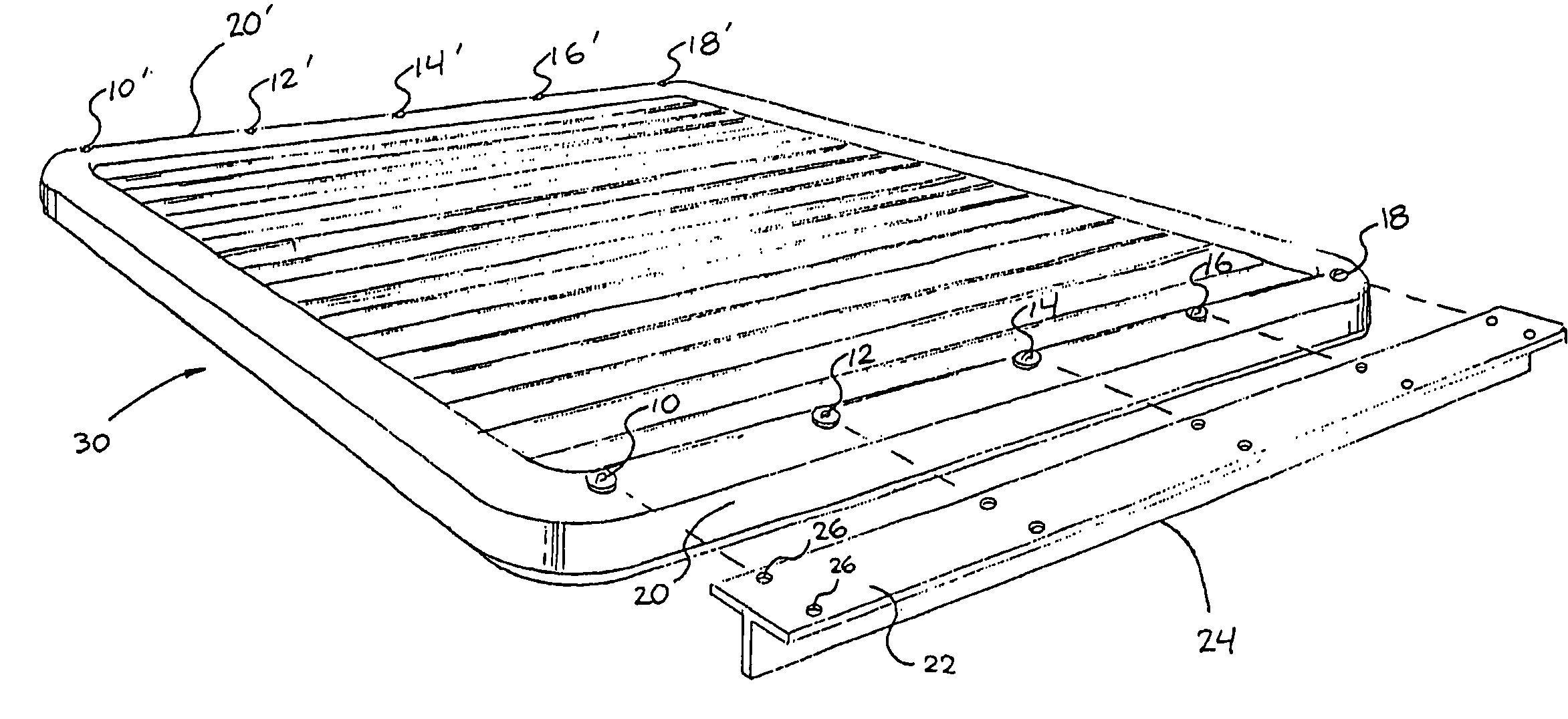
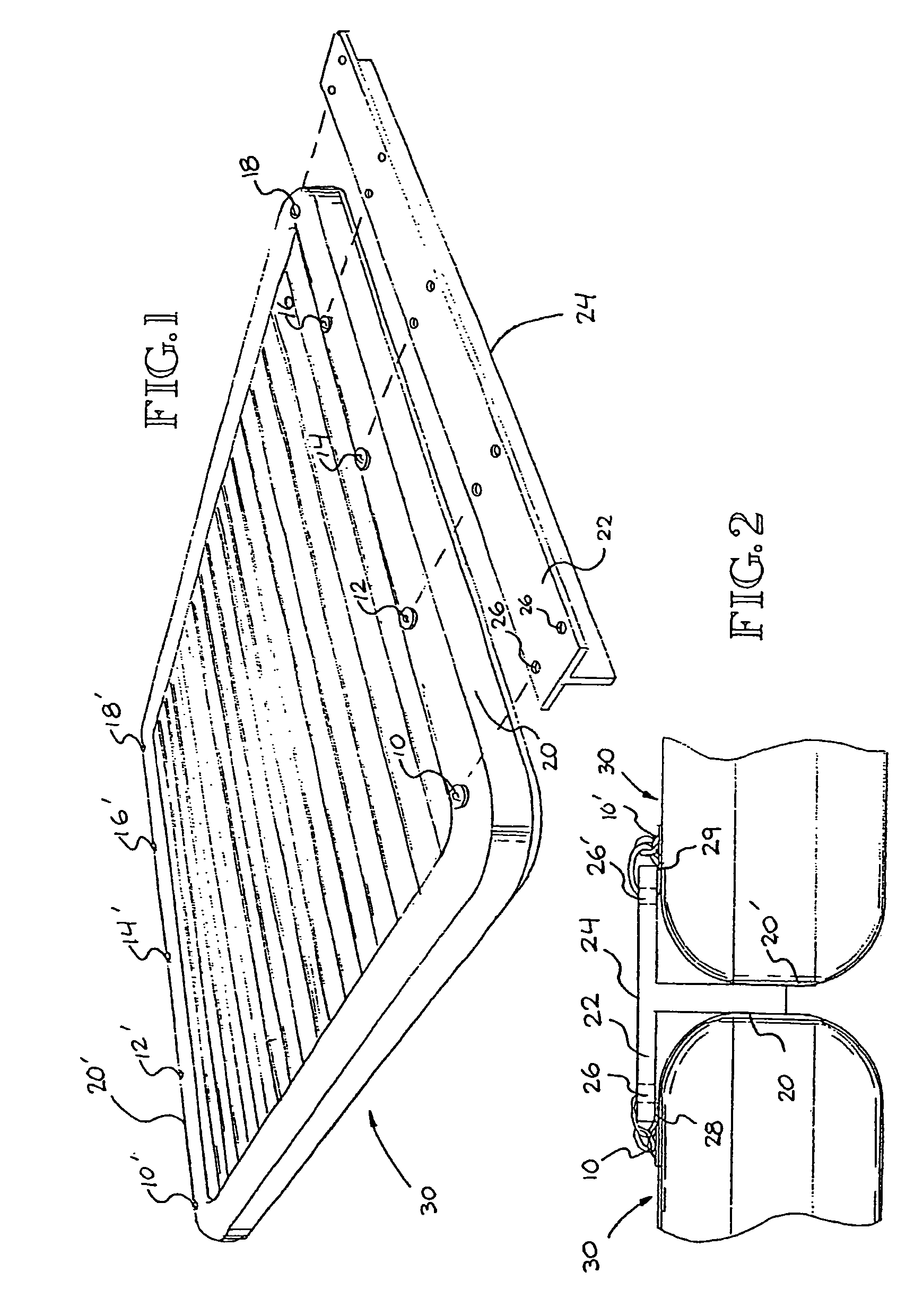
[0027]Turning now to the drawings, the modular floating platforms disclosed herein will be described in preferred embodiments by reference to the numerals of the drawing figures wherein like numbers indicate like parts. FIG. 1 shows a single inflatable module 30, which constitutes a substantially square shape in plan view, and has a vertical dimension established by the height of the inflatable bladders or chambers used. The inflatable module 30 has connectors (such as D-rings) affixed along the outside edges of the module to enable multi-point attachment to adjacent modules, other water vessels, or fixed objects. The connectors are positioned along edges of the inflatable module 30 at locations 10, 10′, 12, 12′, 14, 14′, 16, 16′, 18 and 18′ as shown in FIG. 2. Attachment is made using connector devices such as webbing straps, ropes, caribiners, snap locks and the like. In one preferred embodiment, the connector means is a system of stainless D-rings and several layers of fabric PVC...


PUM


Abstract

A floating platform that has a flat low profile for use by swimmers, divers, boaters, and those engaged in other activities on water. The platform is used alone or as a module in combination with other such floating platform modules; attaching the modules to form a larger floating platform. In a preferred embodiment, the surface of the platform is provided with several connection points enabling multi-point attachment to other vessels and stationary objects, anchor straps and towing straps, and apertures configured to accommodate beverage containers, coolers, chairs, umbrellas, retractable tops and the like. In another embodiment, a detachable cover is attached to the module, the cover forming the floating platform surface. A stable platform and low profile are achieved through use of stiffeners integrated within the platform surface.

Description

CROSS-REFERENCE TO RELATED APPLICATION[0001]This application is a continuation in part of U.S. Utility patent application Ser. No. 10 / 619,655, entitled Modular Floating Swim Platform, filed Jul. 14, 2003 now U.S. Pat. No. 6,805,066 which claims the benefit of Provisional Application No. 60 / 412,264, file Sep. 20, 2002.FIELD OF THE INVENTION[0002]This invention relates to floating structures, and more particularly to modular floating structures that may be used alone or interconnected with a plurality of similar modular units to form varying sizes of floating structures for various applications.BACKGROUND OF THE INVENTION[0003]It is well known to utilize inflatable structures as platforms for use by swimmers, boaters and the like. U.S. Pat. No. 2,888,690 features the use of a watertight rigid frame constructed of wood or sheet metal that has a central main body portion, with outrigged floatation units. This raft is not collapsible or capable of being stowed in a relatively small area....

Claims


Application Information

Patent Timeline
Patent Type & Authority Patents(United States)
IPC IPC(8): B63B35/44B63B3/08B63B22/24B63B35/58
CPCB63B3/08B63B35/58B63B22/24
Inventor JOHNSON, DAVID CYRUS
Owner CONNELLY SKIS
Why Eureka
Try Eureka