Side handles on drill/drivers

a technology of side handles and drills, which is applied in the direction of operator-supported drilling machines, boring/drilling machines, rotary drilling machines, etc., can solve the problems of difficult rotational movement of the collar to different settings, difficult to read the settings of the rotary collar, and difficulty in gaining enough leverage on the drill with the pistol-like grip alone. , to achieve the effect of easy adjustment of the collar and easy reading of the collar settings

Inactive Publication Date: 2006-02-21
BLACK & DECKER INC
View PDF41 Cites 50 Cited by
  • Summary
  • Abstract
  • Description
  • Claims
  • Application Information

AI Technical Summary

Benefits of technology

[0005]With the above deficiency in mind, the present invention provides a drill or driver that includes a housing, a collar mounted at a front portion of the housing, a side handle mounting area provided forward of the collar, a handle mounted to the side handle mounting area, and a chuck mounted forward of the side handle mounting area. With the side handle mounted in front of the collar, easier adjustment of the collar and easier reading of the collar settings is achieved. In addition, because the handle mounting area can be made generally the same size as the chuck, the use of handles with industry standard size mounting collars is also permitted.

Problems solved by technology

However, sometimes it is particularly difficult to gain enough leverage on the drill with the pistol-like grip alone.
However, when a drill that contains either the means for changing speeds or means for applying variable torque also contains a side handle, the placement of the side handle may make it difficult to rotationally move the collar to different settings and also difficult to read the settings on the rotary collar.

Method used


Image

  • Side handles on drill/drivers
  • Side handles on drill/drivers
  • Side handles on drill/drivers

Examples


Embodiment Construction

[0014]The following description of the preferred embodiment is merely exemplary in nature and is in no way intended to limit the invention, its application, or uses.

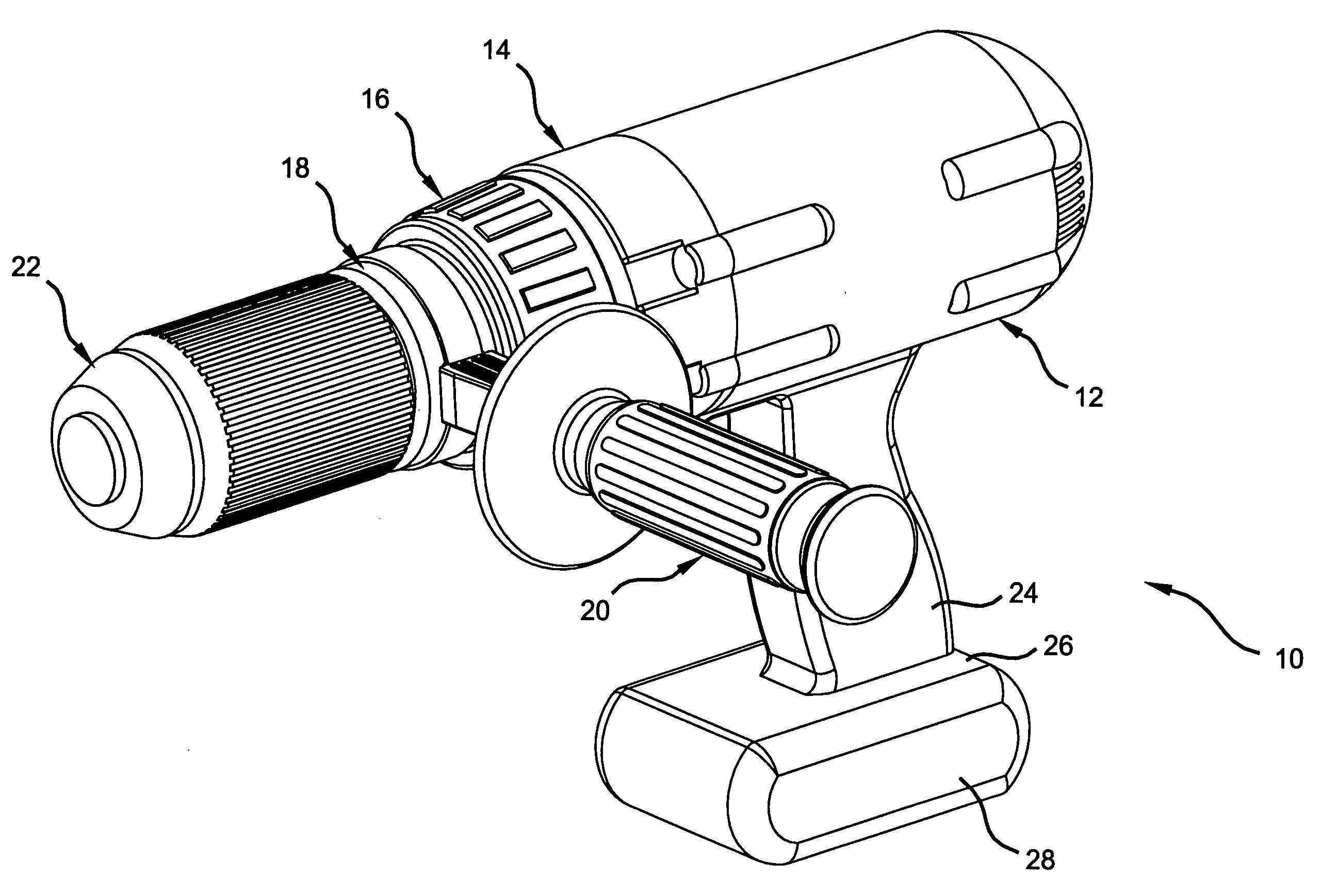
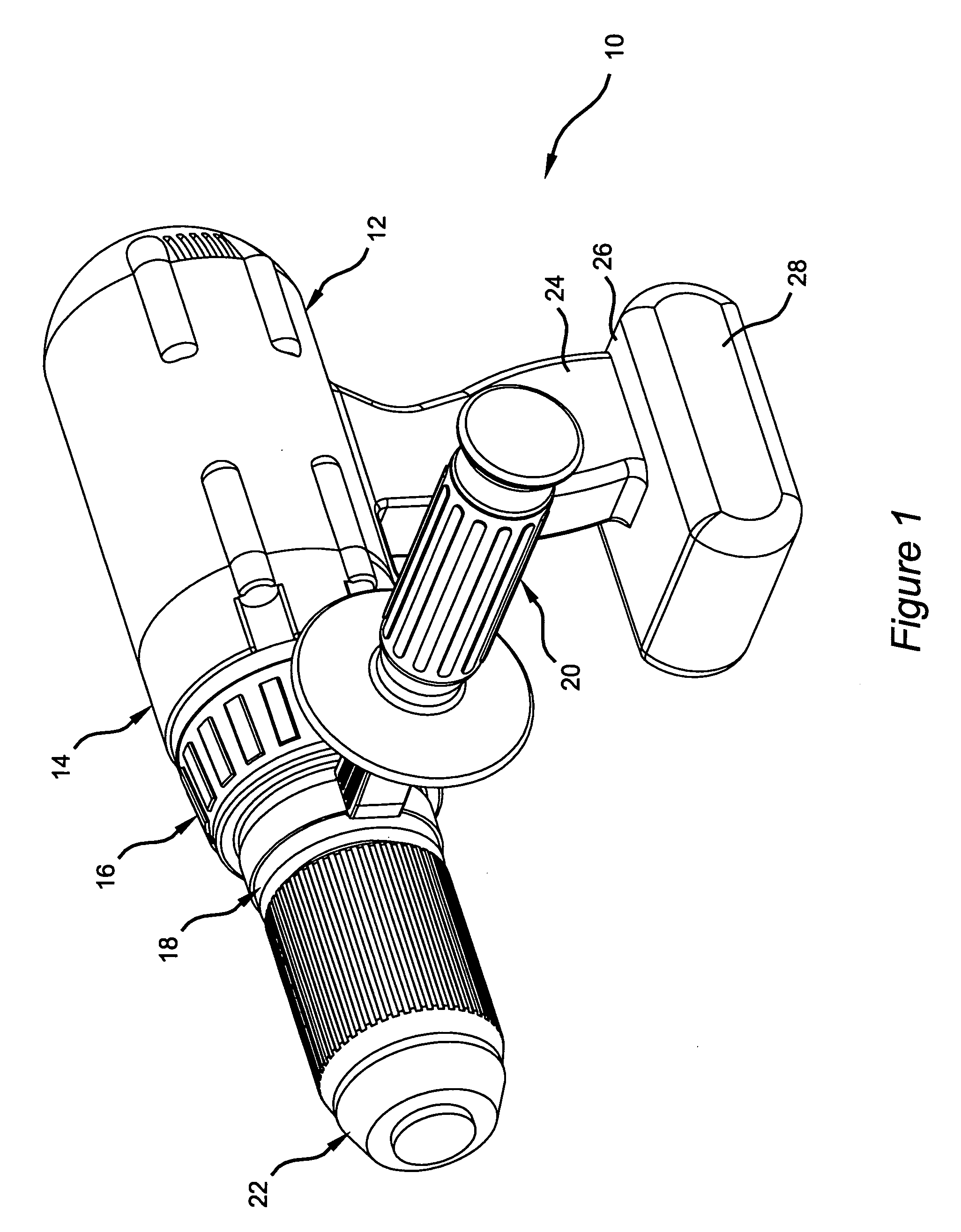
[0015]FIG. 1 shows a tool 10, which can be a drill or driver, of the present invention. As can be seen in FIG. 1, the tool 10 includes a housing 12. A gear case cover 14 is mounted to the housing 12 and a collar 16 is rotatably mounted to the cover 14. A cap 18 is fixedly mounted to the gear case cover 14 and defines a side handle mounting area to provide an area to secure a side handle 20. A chuck 22 is mounted forward of the cap 18. The chuck 22 can be used to hold a drill bit or some other type of bit.

[0016]The housing 12 includes a pistol like grip 24 and a trigger switch (not shown) that is used to turn the tool 10 on or off. The housing 12 also has a wide base 26 that holds a battery pack 28. The housing 12 encloses an electric motor (not shown). Although the exemplary housing 12 shown contains these features, any ...


PUM

PropertyMeasurementUnit
angleaaaaaaaaaa
outer diameteraaaaaaaaaa
torqueaaaaaaaaaa

Abstract

A drill / driver is provided that includes a housing, a collar mounted at a front portion of the housing, a side handle mounting area provided forward of the collar, a handle mounted to the side handle mounting area, and a chuck mounted forward of the side handle mounting area. With the side handle mounted in front of the collar, easier access to the adjusting collar and easier reading of the collar settings is achieved.

Description

CROSS-REFERENCE TO RELATED APPLICATIONS[0001]This application is a continuation of U.S. patent application Ser. No. 10 / 612,384 filed on Jul. 2, 2003 now U.S. Pat. No. 6,776,244, which is a continuation of U.S. patent application Ser. No. 10 / 028,461 filed on Dec. 20, 2001 now U.S. Pat. No. 6,595,300. The disclosures of the above applications are incorporated herein by reference.FIELD OF THE INVENTION[0002]The present invention relates to power tools, and more particularly, to a power drill, driver, or hammer drill having a side handle arrangement.BACKGROUND OF THE INVENTION[0003]A typical power drill or driver includes a housing, a spindle, and a chuck for holding a drill bit or screwdriver. The housing typically includes a portion which contains an electric motor, a pistol-like grip for holding the drill, and a trigger switch for turning the drill on and off so as to supply torque to the drill bit or screwdriver for drilling a hole and inserting or removing a screw or the like. Howe...

Claims


Application Information

Patent Timeline
Patent Type & Authority Patents(United States)
IPC IPC(8): B23B45/02B23B45/00B25B21/00B25F5/00B25F5/02
CPCB25B21/00B25F5/001B25F5/026Y10T16/48Y10T408/96B23B45/02
Inventor MILBOURNE, RODNEY
Owner BLACK & DECKER INC
Why Eureka
Try Eureka