Vacuum flow suction cup assembly

a technology of vacuum flow and suction cup, which is applied in the direction of manipulators, load-engaging elements, gripping heads, etc., can solve the problems of reducing the vacuum inside the plenum, reducing the vacuum of the plenum, and unable to expose the object or object to be picked to sufficient vacuum to permit picking

Inactive Publication Date: 2006-02-21
AMF AUTOMATION TECH
View PDF4 Cites 39 Cited by
  • Summary
  • Abstract
  • Description
  • Claims
  • Application Information

AI Technical Summary

Problems solved by technology

With such an arrangement, there is always a loss of vacuum from through any suction cup that does not engage a product being picked.
If the object or objects being picked do not cover all of the vacuum assisted suction cups from a single plenum, then leakage due to the uncovered suction cups will cause a reduction of the vacuum inside of the plenum and the object or objects that are to be picked may not be exposed to adequate vacuum to permit their picking.
Thus, problems arise when the objects to be picked do not cover all of the suction cup

Method used


Image

  • Vacuum flow suction cup assembly
  • Vacuum flow suction cup assembly
  • Vacuum flow suction cup assembly

Examples


Embodiment Construction

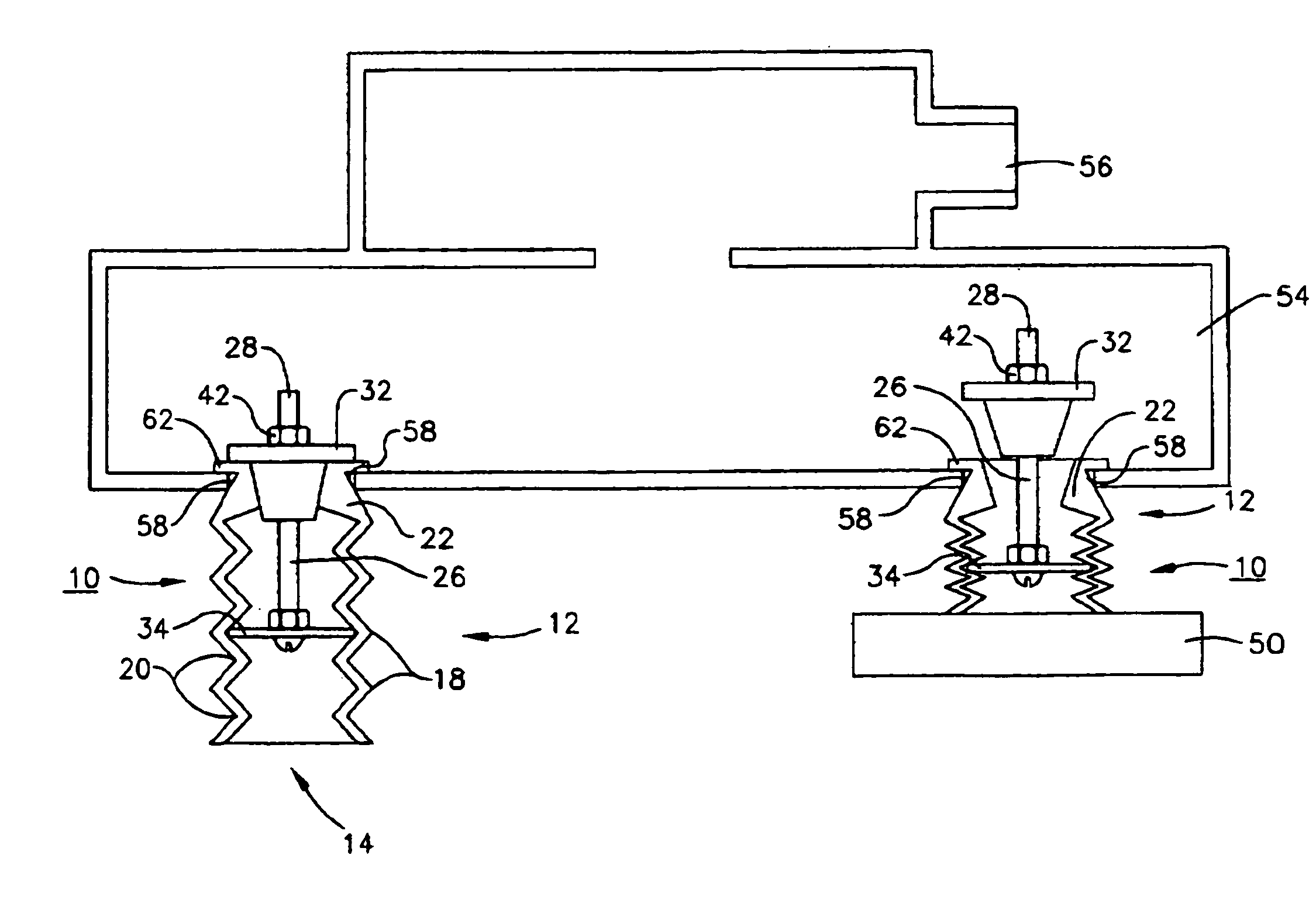
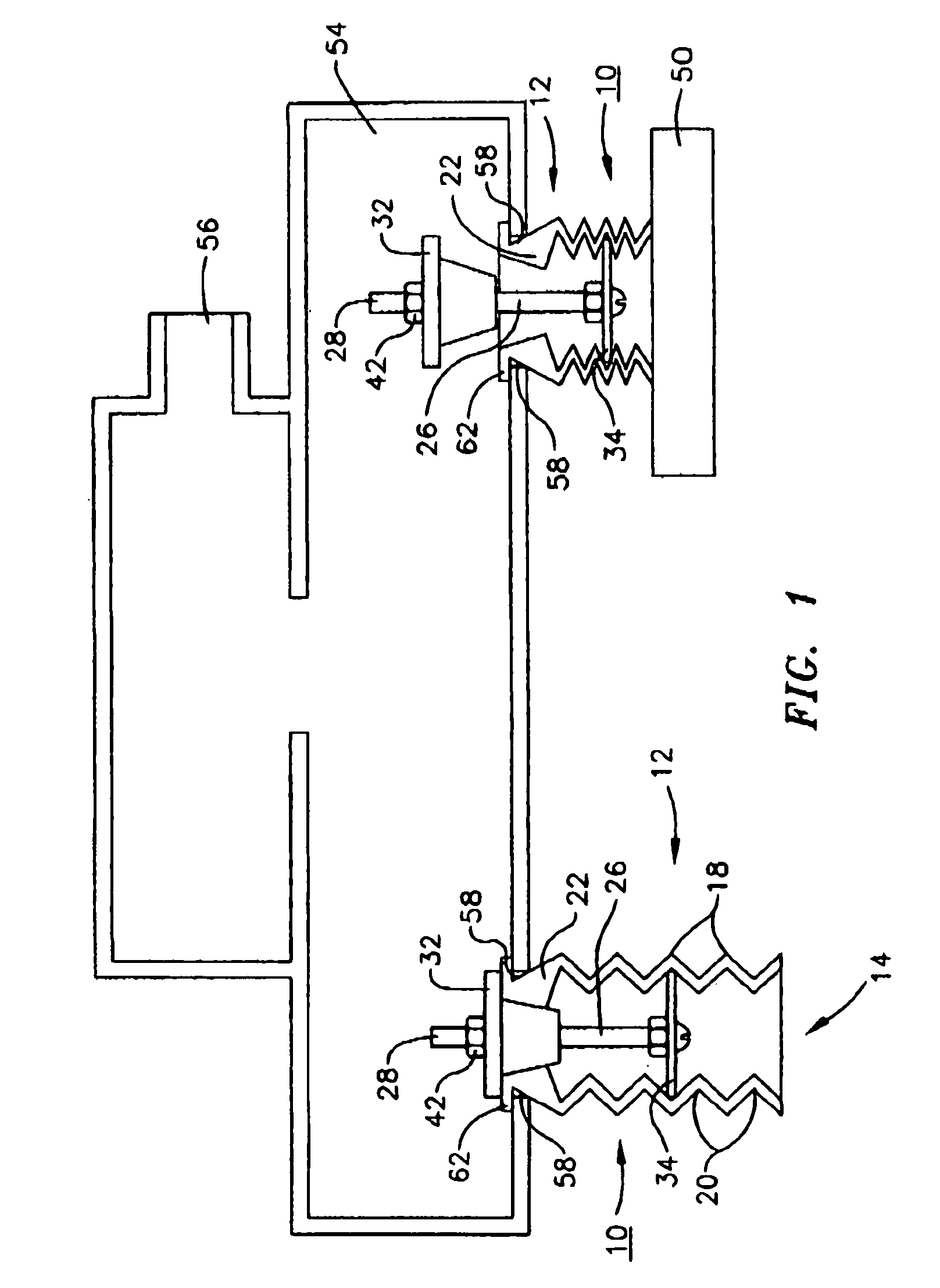
[0015]Referring now to FIGS. 1 and 3–6, the contact activated vacuum assisted suction cup assembly 10 of the present invention comprises a corrugated or bellowed cup 12 comprising an open end 14 and a valve end 16. Corrugated cup 12 further includes coaxial large diameter areas 18 and small diameter areas 20 defined by the interconnected corrugations or “bellowed” configuration of bellowed cup 12.

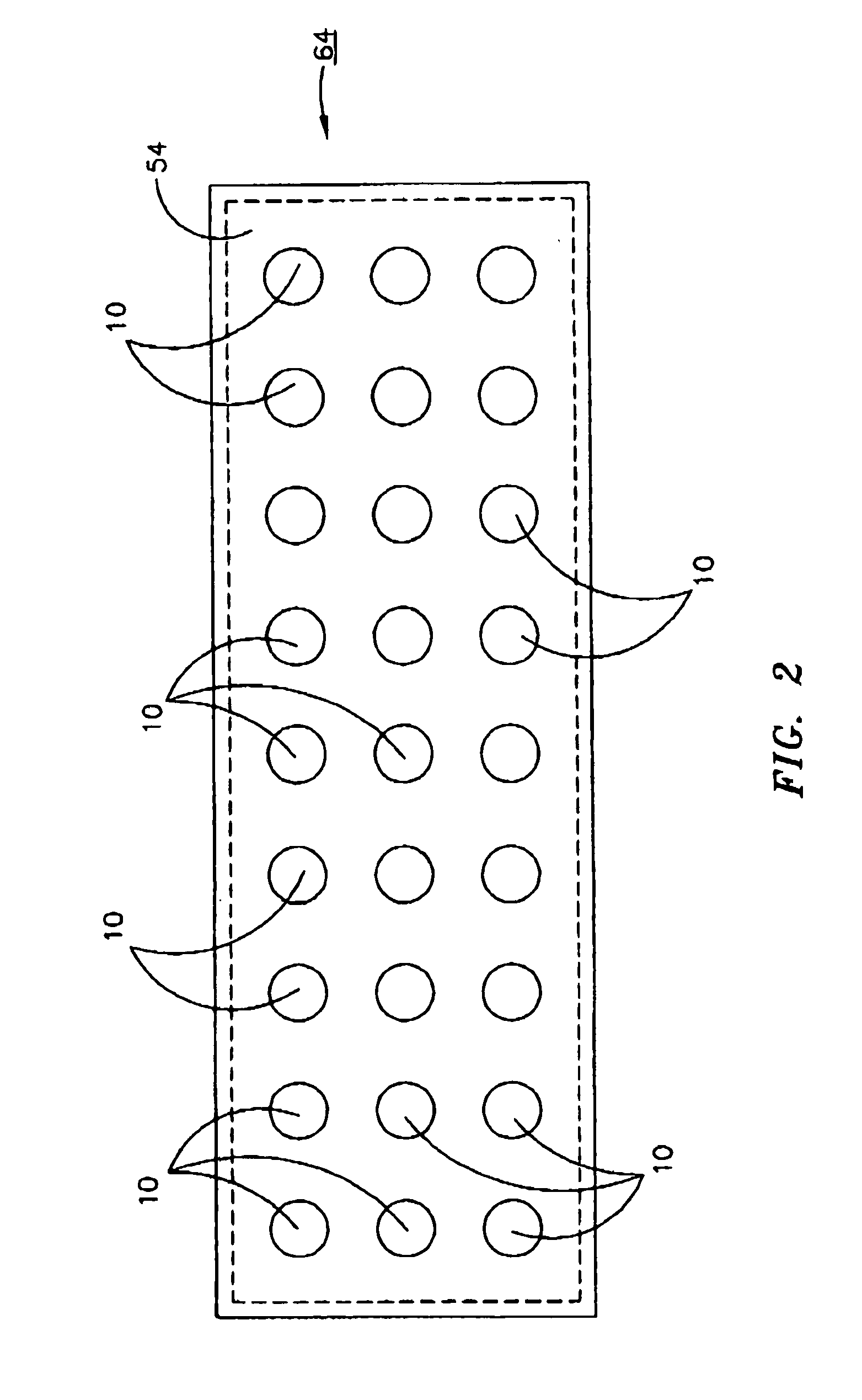
[0016]At the valve end 16 of bellowed cup 12 is a valve seat 22 (best seen in FIGS. 1 and 3) that closes valve end 16 except at the aperture 24 in valve seat 22. Valve end 12 also incorporates a peripheral and preferably integral flange 62 whose purpose is the engagement of apertures in a plenum 54 as described below.

[0017]Inserted through aperture 24 is valve stem 26 (best seen in FIGS. 1 and 6). As depicted on the attached drawings, valve stem 26 comprises a simple bolt, however it will be readily appreciated that more sophisticated custom machined, welded etc. structures could be substit...


PUM


Abstract

A contact activated vacuum assisted suction cup assembly comprising: 1) a cylindrical bellowed or corrugated cup defining a plurality of interconnected bellows or corrugations of alternating, coaxial large and small diameter areas, hereinafter “bellows”, and having; A) an open contact end; and B) a valve end including a valve seat; 2) a valve stem having first and second extremities; 3) a valve plate intermediate the open contact end and the valve end in one of the large diameter areas attached to the first extremity; and 4) a valve stop attached to the valve stem at the second extremity that can engage the valve seat in the closed position. A picking device comprising a vacuum plenum having a plurality of the previously described contact activated vacuum assisted suction cup assemblies mounted therein in plenum apertures that engage a peripheral flange about the valve end is also described.

Description

FIELD OF THE INVENTION[0001]The present invention relates to vacuum assisted suction cups and more particularly to such devices that are used in combination with vacuum plenums to pick up and move individual units in, for example, a packaging operation.BACKGROUND OF THE INVENTION[0002]In the packaging and other similar industries where it is desired to pick up (in the idiom of the industry “pick”) a unit, for example a loaf of bread, a manufactured part or assembly etc., vacuum assisted suction devices are commonly used. Such devices generally and commonly comprise a large vacuum plenum with many vacuum assisted suction cups, i.e. cup shaped devices to which a vacuum is applied from the interior of the plenum, attached thereto. With such an arrangement, there is always a loss of vacuum from through any suction cup that does not engage a product being picked. If the object or objects being picked do not cover all of the vacuum assisted suction cups from a single plenum, then leakage ...

Claims


Application Information

Patent Timeline
IPC IPC(8): B25J15/06
CPCB65G47/917B25J15/0616
Inventor PORRAS, CHRISPARNELL, GEOFFBOYD, PAULROBINSON, LEE
Owner AMF AUTOMATION TECH
Why Eureka
Try Eureka