
High pressure barrier to oil loss by diffusion

Inactive Publication Date: 2006-02-21
SEAGATE TECH LLC
View PDF43 Cites 17 Cited by
  • Summary
  • Abstract
  • Description
  • Claims
  • Application Information

AI Technical Summary

Benefits of technology

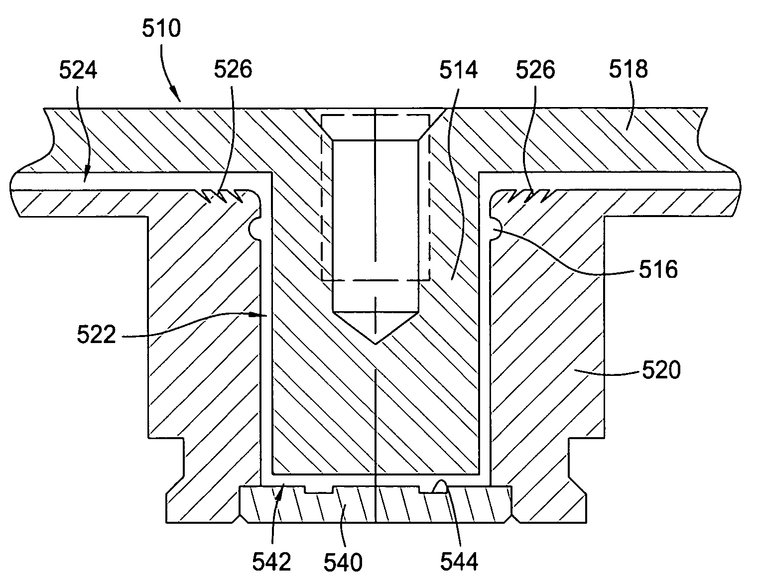
[0027]A capillary seal is provided in the vertical fluid gap at one end. Preferably, the capillary seal is disposed at an upper end of the shaft proximal to the upper hub portion. In addition, air pumping grooves are machined along the horizontal fluid gap. The air pumping grooves may be machined into the bottom of the upper hub portion; preferably, though, they are machined into the top of the sleeve. The air pumping grooves are used to create a high pressure region in the vicinity of the capillary seal. In this respect, the high pressure barrier reduces the number of oil molecules diffusing out of the capillary seal and, therefore, the total oil loss from the system.

Problems solved by technology

In this respect, mechanical bearings are not always scaleable to smaller dimensions.
More significantly, in some conditions ball bearings generate unwanted vibrations in the motor assembly, causing the read / write head to become misaligned over the tracks.
Still further, there is potential for leakage of grease or oil into the atmosphere of the disc drive, or outgassing of the components into this atmosphere.
However, air cannot provide the lubricating qualities of oil or the load capacity.
A drawback to the use of liquid is that the liquid lubricant should be sealed within the bearing to avoid leakage.
Any loss in fluid volume results in a reduced bearing load capacity and life for the motor.
In this respect, the physical surfaces of the spindle and of the housing would come into contact with one another, leading to accelerated wear and eventual failure of the bearing system.
One problem presented with the capillary seal design is that an end of the bearing gap is exposed to the ambient environment of the disc drive housing.
This, in turn, can lead to a slow but progressive oil loss by evaporation.
Nevertheless, over the life of the motor a noticeable amount of lubricant is lost from the capillary seal by evaporation, as well as from vapor diffusion in the gas phase.
However, the available reservoir volume is limited by geometrical size constraints and by requirements for seal splash robustness during shock events.

Method used


Image

  • High pressure barrier to oil loss by diffusion
  • High pressure barrier to oil loss by diffusion
  • High pressure barrier to oil loss by diffusion

Examples


Embodiment Construction

[0037]The present invention provides an improved spindle motor arrangement. The improved motor employs novel air pumping grooves as a means for retaining liquid lubricant within a fluid bearing interface.

[0038]FIG. 5 presents a cross-sectional view of an improved spindle motor arrangement 500 in one embodiment in which air pumping grooves 526 are machined. The motor 500 first comprises a hub 510. The hub 510 provides a radial shoulder 512 for receiving and supporting a body to be rotated, such as a magnetic disc (not shown). The hub 510 defines a central shaft portion 514 and a horizontal body portion 518. The shaft 514 is configured for constant high speed rotation. This rotation is established by a stator 552 which is mounted from a base 560. The stator 552 defines an electric coil that, when energized, creates a magnetic field. The energized coil cooperates with magnets 550 mounted from the inner surface of the hub 510 to generate rotational movement of the hub 510.

[0039]As noted...


PUM


Abstract

An improved rotational motor, such as a spindle motor for a disc drive, is provided. The motor first comprises a hub having a shaft portion and a horizontal body portion. The motor also comprises a sleeve surrounding the shaft portion of the hub. A fine vertical gap is retained between the shaft and the inner diameter of the surrounding sleeve. In addition, a fine horizontal gap is provided between the upper hub portion and the top of the sleeve. The vertical gap is filled with a lubricating liquid, such as a clean oil. A capillary seal is provided in the vertical fluid gap at one end. Preferably, the capillary seal is disposed at an upper end of the shaft proximal to the horizontal gap. Novel air pumping grooves are machined along the horizontal fluid gap. When the hub is rotated, the air pumping grooves create a high pressure region in the vicinity of the capillary seal. This forms a high pressure barrier that reduces the number of oil molecules diffusing out of the capillary seal and, therefore, inhibits oil loss from the system.

Description

CROSS-REFERENCE TO RELATED APPLICATIONS[0001]This new application for letters patent claims priority from an earlier-filed provisional patent application entitled “High Pressure Barrier to Oil Loss by Diffusion.” That application was filed on Apr. 21, 2003 and was assigned application Ser. No. 60 / 464,482.BACKGROUND OF THE INVENTION[0002]1. Field of the Invention[0003]The present invention relates to fluid dynamic bearing motors. More specifically, the present invention pertains to fluid dynamic bearing motors such as are used to support and rotationally drive one or more memory discs.[0004]2. Description of the Related Art[0005]The computer industry employs magnetic discs for the purpose of storing information. This information may be stored and later retrieved using a disc drive system. Computer systems employ disc drive systems for transferring and storing large amounts of data between magnetic discs and the host computer. The magnetic discs are typically circular in shape (though...

Claims


Application Information

Patent Timeline
IPC IPC(8): F16C32/06F16C33/74F16C17/10F16C33/10G11B19/20
CPCF16C17/045F16C17/10F16C33/107F16C41/008G11B19/2009F16C33/74F16C2370/12
Inventor DITTMER, DANIEL D.PARKHOMOVSKY, ALEXANDER
Owner SEAGATE TECH LLC
Learn More