Dual water injector for primary and idle relief exhaust passages

a technology of exhaust passage and water injector, which is applied in the direction of propulsive elements, vessel construction, marine propulsion, etc., can solve problems such as severe corrosion

Inactive Publication Date: 2006-02-21
BRUNSWICK CORPORATION
View PDF12 Cites 47 Cited by
  • Summary
  • Abstract
  • Description
  • Claims
  • Application Information

AI Technical Summary

Problems solved by technology

As a result, fluid expelled from the spray ring will not migr

Method used


Image

  • Dual water injector for primary and idle relief exhaust passages
  • Dual water injector for primary and idle relief exhaust passages
  • Dual water injector for primary and idle relief exhaust passages

Examples


Embodiment Construction

[0023]Throughout the description of the preferred embodiment of the present invention, like components will be identified by like reference numerals.

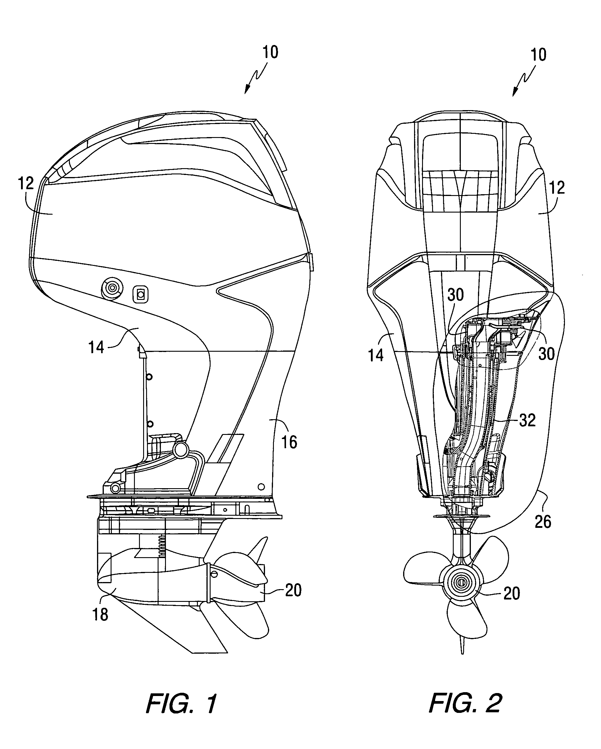
[0024]FIG. 1 is a side view of an outboard motor 10. A cowl structure 12 encloses an internal combustion engine, which will be described in greater detail below, with a lower cowl structure 14 enclosing an adapter plate on which the engine is supported. Side covers, or chaps 16, enclose a driveshaft housing which will be described in greater detail below. A gear case 18 is supported by the driveshaft housing and, in turn, supports a propeller shaft for rotation about a horizontal axis. A propeller 20 is attached to the propeller shaft for rotation with the propeller shaft.

[0025]FIG. 2 is a rear view of the outboard motor 10 showing the cowl structure 12, the lower cowl structure 14, the propeller, and a cutaway portion 26 which exposes a portion of the adapter plate 30 and the driveshaft housing 32.

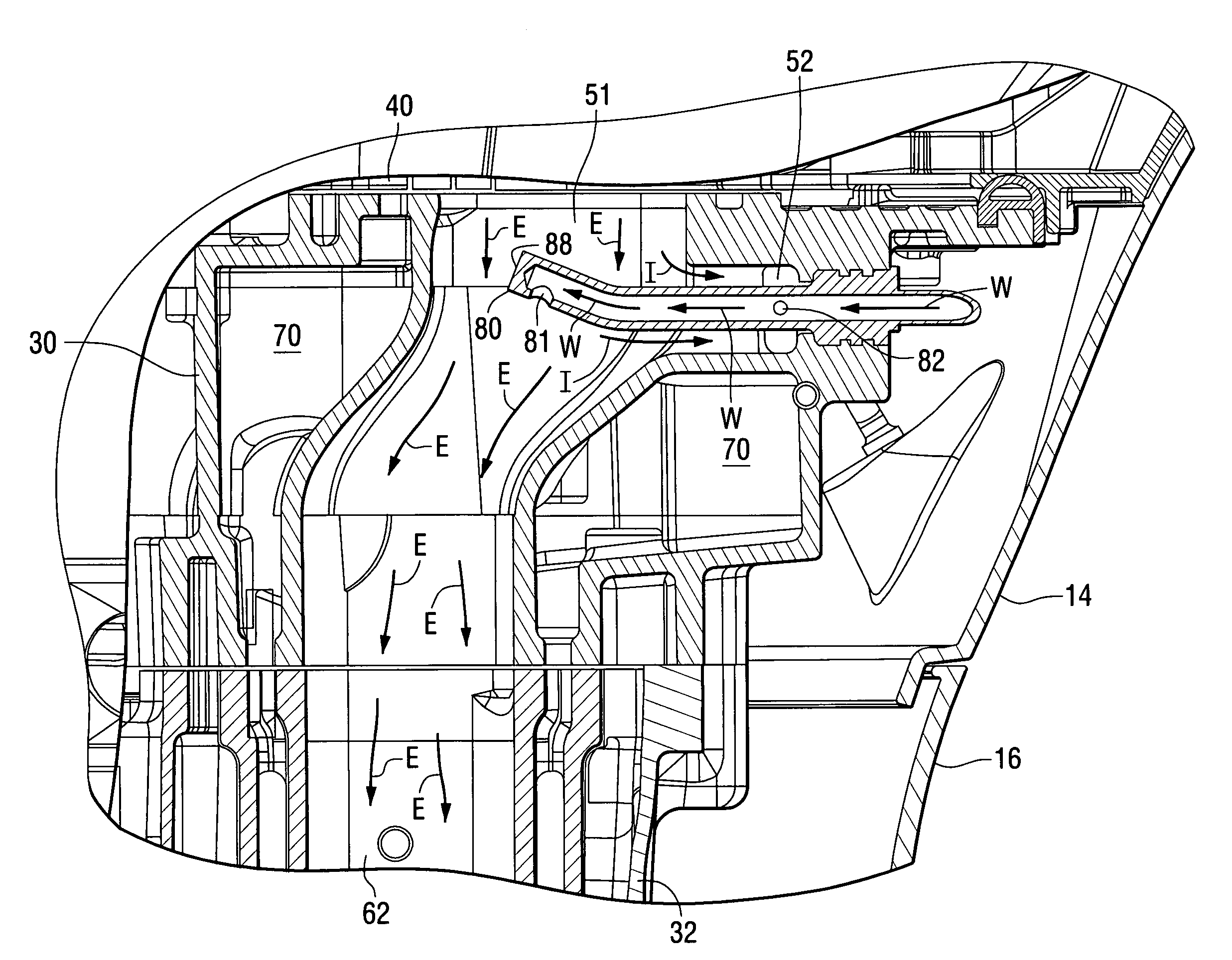
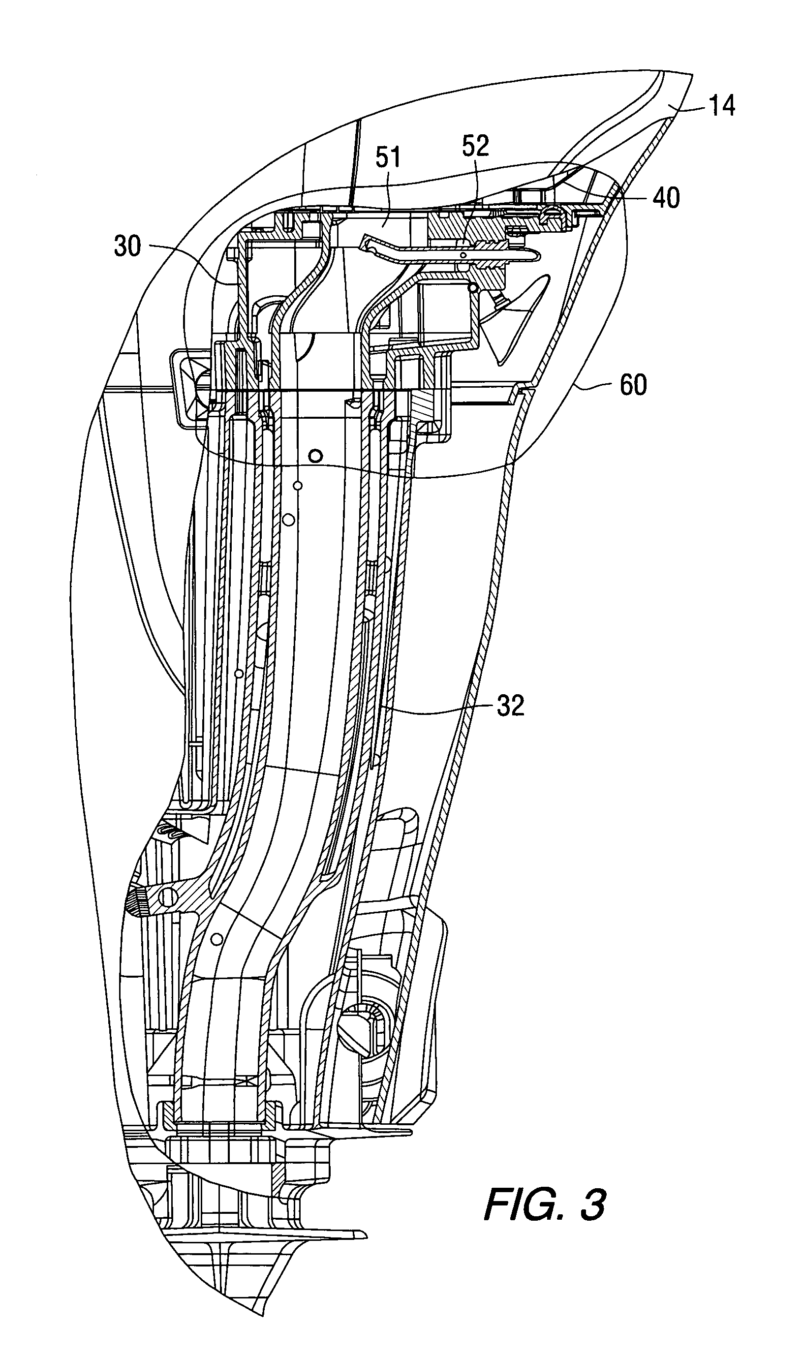
[0026]FIG. 3 is an enlarged view of th...


PUM


Abstract

A water cooling system for an outboard motor provides a water conduit that extends through both an idle exhaust relief passage and a primary exhaust passage. Water within the water conduit flows through first and second openings to distribute sprays or streams of water into first and second exhaust conduits which can be the primary and idle exhaust relief passages of an outboard motor.

Description

BACKGROUND OF THE INVENTION[0001]1. Field of the Invention[0002]The present invention is generally related to a water injector for use in conjunction with exhaust passages and, more particularly, to a system by which water is injected from a common conduit into both the primary and idle relief exhaust passages of an outboard motor.[0003]2. Description of the Prior Art[0004]Those skilled in the art of marine propulsion systems and, more particularly, outboard motors, are familiar with various ways of cooling the exhaust gases emitted by an internal combustion engine of a marine propulsion system. One known method of reducing the temperature of exhaust gas, as it flows from an internal combustion engine to an exhaust pipe and is emitted from the marine propulsion system, is to spray water directly into the exhaust gas stream. Other methods include the provision of water jackets and other water reservoir cavities to absorb heat from structures through which the exhaust gases pass.[0005...

Claims


Application Information

Patent Timeline
IPC IPC(8): B63H21/38
CPCB63H20/245B63B2770/00
Inventor HALLEY, STUART M.BELTER, DAVID J.
Owner BRUNSWICK CORPORATION
Why Eureka
Try Eureka