Method of controlling a threshing mechanism of a combine harvester

a combine harvester and threshing mechanism technology, which is applied in baling, lighting and heating equipment, agriculture tools and machines, etc., can solve the problems of not being able to always maintain the targeted optimal nominal crop throughput, the driving operator is not easy to adjust all working unit parameters, and the loss increases as well. achieve the effect of fast and simple automatic reaction

Active Publication Date: 2006-02-21
CLAAS SELBSTFAHRENDE ERNTEMASCHINEN GMBH
View PDF14 Cites 32 Cited by
  • Summary
  • Abstract
  • Description
  • Claims
  • Application Information

AI Technical Summary

Benefits of technology

[0011]Accordingly, it is an object of the present invention to provide a method of controlling and a corresponding combine harvester, which allow a fast and simple automatic reaction to the occurrence of restrictive harvesting conditions.

Problems solved by technology

Unfortunately these objectives are not independent from one another, but instead with increasing crop throughput, generally the losses increase as well.
Due to different properties of the different crop or fruit types, as well as different harvesting conditions such as ripening condition of the crop, grain moisture, straw content, straw moisture, grain size, components density, etc. it is often not simple for a driving operator to adjust all parameters of the working units of the combine harvester.
Unfortunately, however the targeted optimal nominal crop throughput can not be always maintained, since suddenly occurring restricting harvesting conditions do not allow the required harvesting speed.
Such restricting outer harvesting conditions include for example a so-called down grain, product flow problems in the cutting mechanism, rocky regions in the ground, strong ground unevenness or an overloading of the crop during the travel.
Also, outer harvesting additions can lead to the situation that the driver must suddenly increase the harvesting speed, for example when there is a risk that the weather changes and a predetermined field part must be definitely harvested before it.
All these cases lead to the situation that the concrete actual crop throughput deviates from the nominal crop throughput, with respect to the optimal adjustment of the machine parameters.
Each significant deviation of the crop throughput from nominal crop throughput is however disadvantageous, depending on whether it deals with too low or too high crop throughput.
When mainly the actual crop throughput is lower than the nominal crop throughput this can lead to the situation that the threshing device of the combine harvester thrashes very small crop quantity too strongly.
As a result, many grains are broken in the threshing device (so-called “grain breakage”).
The damaged grains can not be used anymore, so that the loss rate is increased.
Furthermore, with the too hard threshing, the straw is unnecessarily comminuted in the threshing device and moves then through the threshing concave or through the subsequent separating device into the cleaning device.
This leads to an increased cleaning load and a reduced cleaning efficiency.
The different crop properties can further lead to overloading of individual working units, for example the separation rotors, a straw chopper or the drive motor.
Very high crop throughput to the contrary leads to the situation that the crop is no longer correctly threshed in the threshing device.
The not threshed grains can not be then separated in the subsequent separating device from straw, so that an increased number of grains remains in the straw and thereby the loss rate also increases.
New adjustments of the different parameters are therefore proposed continuously to the driver of the combine harvester during a harvesting work, that additionally burdens the driver and additionally distracts him from the important task to adjust the traveling speed to the outer conditions and to reach the optimal harvesting speed as fast as possible.

Method used


Image

  • Method of controlling a threshing mechanism of a combine harvester
  • Method of controlling a threshing mechanism of a combine harvester
  • Method of controlling a threshing mechanism of a combine harvester

Examples


Embodiment Construction

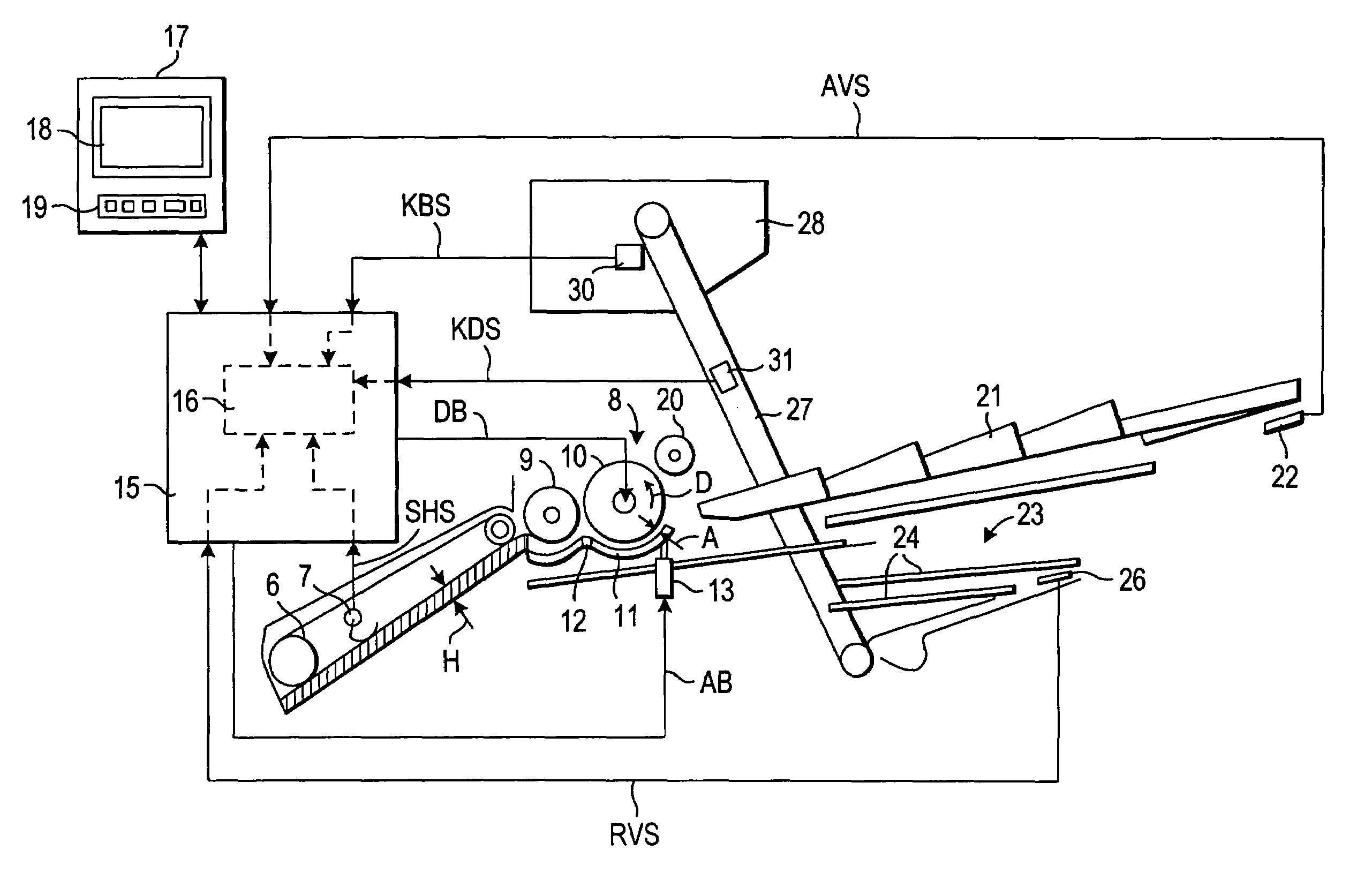
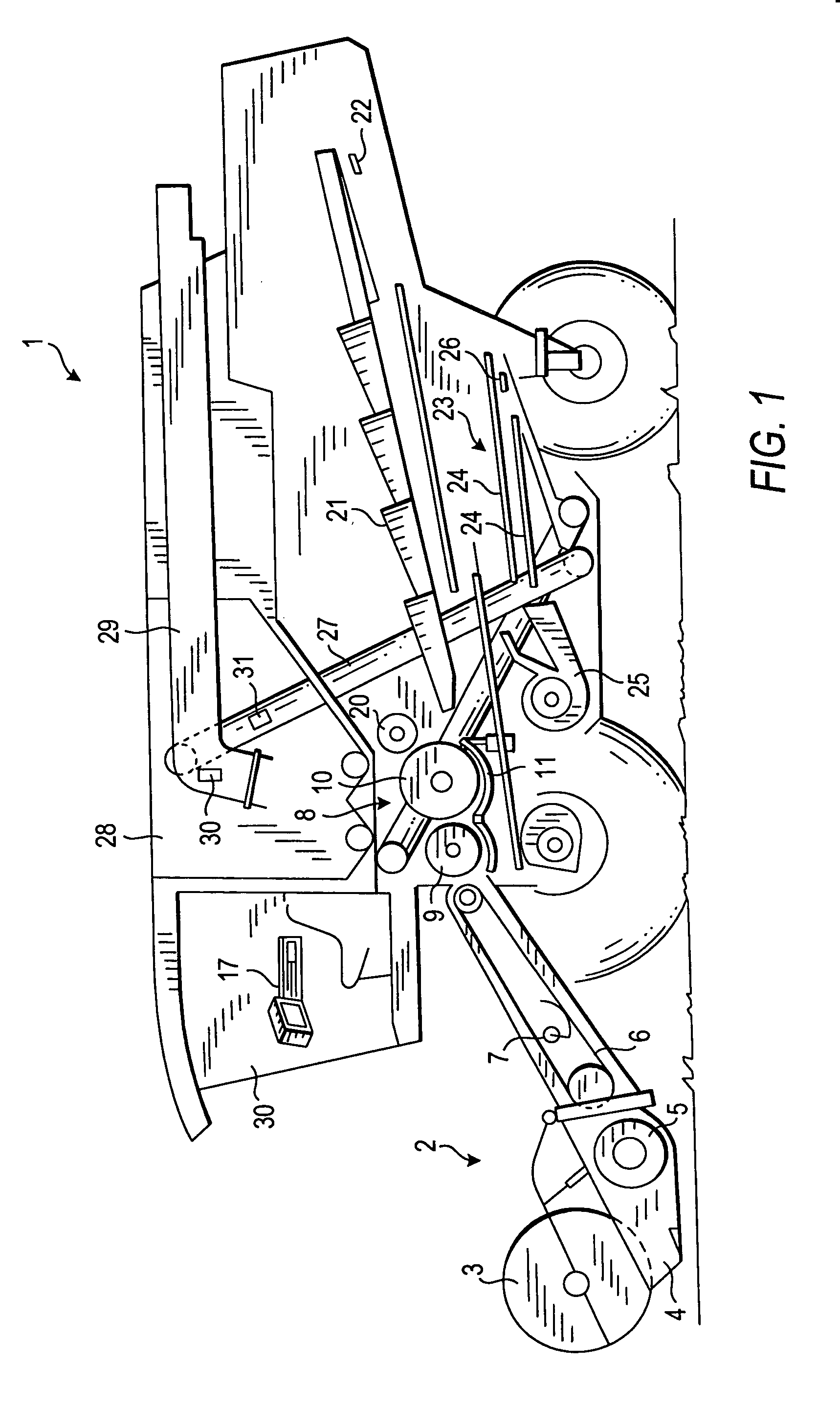
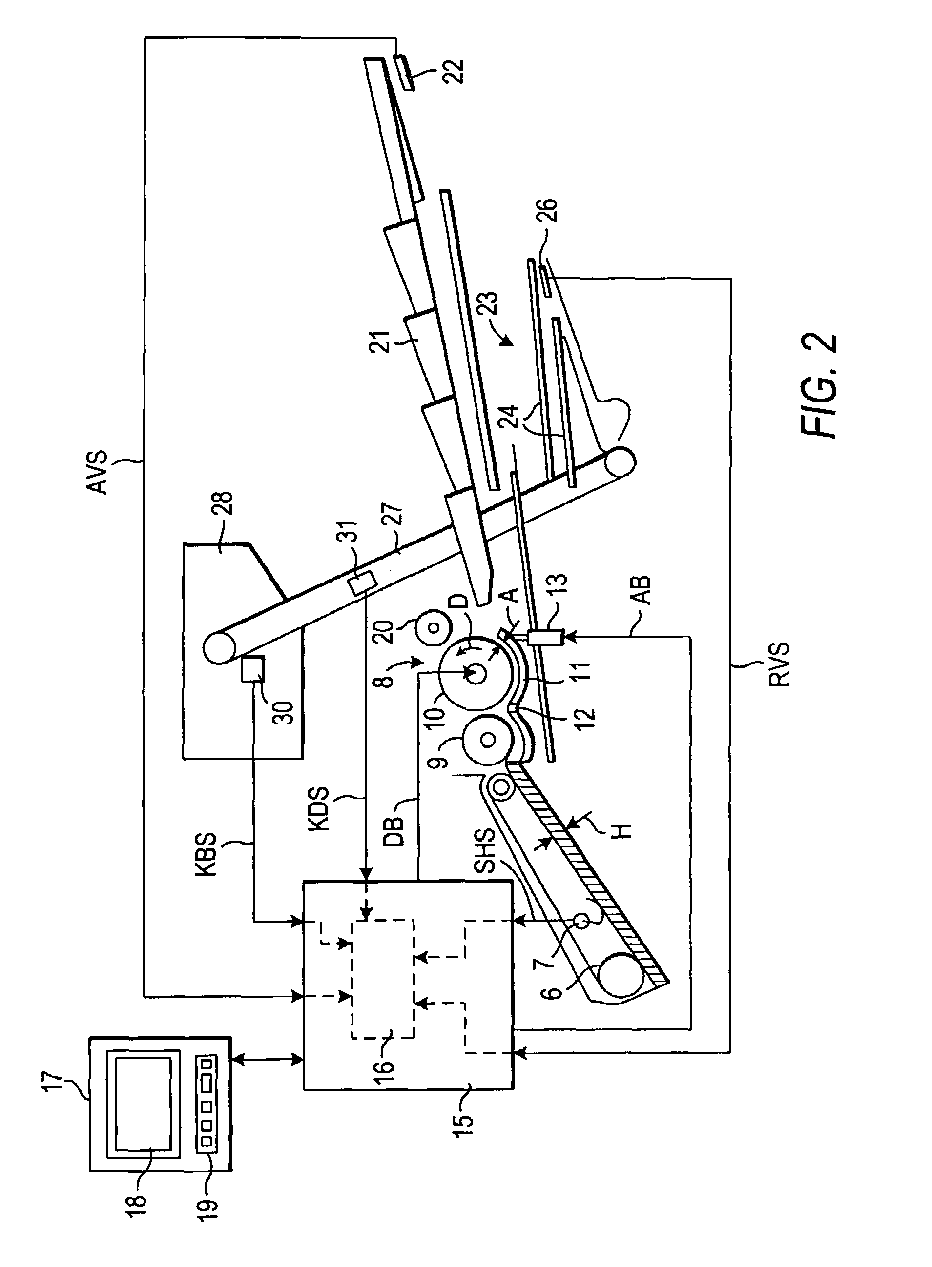
[0030]As an example of the present invention, a self-propelling combine harvester is shown in FIG. 1 and identified with reference numeral 1. It has a so-called tangential or also a transverse flow threshing mechanism 8, and a shaker 21 arranged behind and operating as a separating device. The shaker 21 is formed as a hurdle shaker provided with several shaker traveling stages. Under the shaker 21, a cleaning device 23 is located. It is includes several sieves 24 which are arranged over one another, and also a fan 25. The invention of course is not limited to the combine harvester of this specific type.

[0031]The combine harvester 1 in accordance with the present invention operates in the following manner.

[0032]The crop is first inclined by a reel 3 of the mowing table 2 in direction of a mowing direction 4 and cut by the mowing knives. The crop is then transported through a feed anger 5 and an inclined conveyor into a feed passage 6 to the inlet of the threshing mechanism 8.

[0033]A ...


PUM


Abstract

For controlling a threshing mechanism of a combine harvester parameters of the threshing mechanism are adjusted with respect to a nominal crop throughput determined for corresponding harvesting conditions to an optimal value, the changing automatically and the adjustment includes automatically determining a deviation of an actual crop throughput from the nominal crop throughput, and adjusting at least one threshing mechanism parameter for adaptation to the actual crop throughput; also a combine harvester with the control device for performing the method is proposed.

Description

BACKGROUND OF THE INVENTION[0001]The present invention relates to a method of controlling a threshing mechanism of a combine harvester.[0002]More particularly, it relates to such a method of controlling, in accordance with which the predetermined parameters of the threshing mechanism are adjusted with regard to a nominal crop performance determined for predetermined harvesting conditions, to an optimal value.[0003]Moreover, the present invention also relates to a combine harvester provided with a control arrangement for performing such a method.[0004]Combine harvesters are provided with various working aggregates for treatment of the harvested product stream. Important working aggregates include for example a threshing mechanism for threshing a product stream from which grains have to be removed, a separating device which is located after the threshing mechanism and formed for example as a shaker or a rotor for separating the grains contained in the threshed product stream from furt...

Claims


Application Information

Patent Timeline
Patent Type & Authority Patents(United States)
IPC IPC(8): A01D75/18A01F12/16A01F21/00A01D41/127
CPCA01D41/127
Inventor BEHNKE, WILLIDAMMANN, MARTIN
Owner CLAAS SELBSTFAHRENDE ERNTEMASCHINEN GMBH
Why Eureka
Try Eureka