Urinary flow control device and method

a technology of flow control device and urinary incontinence, which is applied in the field of medical devices, can solve the problems of device component failure, inconvenient use, and persistent urinary incontinence for both men and women, and achieves the effects of reducing the number of devices, and improving the quality of li

Inactive Publication Date: 2006-02-21
SRS MEDICAL SYST INC
View PDF112 Cites 94 Cited by
  • Summary
  • Abstract
  • Description
  • Claims
  • Application Information

AI Technical Summary

Benefits of technology

[0015]Unlatching occurs when an external switch actuator (e.g., a magnet) is introduced exterior but proximal to the body (e.g., in the case of magnetic actuating means, to the anterior region of the body near the pubic bone). Urine flow then begins as the first fluid containing compartment is allowed to deform (i.e., partially collapse) due to fluid being hydraulically shuttled from the first fluid compartment to an adjacent reservoir (i.e., from the first to second fluid containing compartments). This dynamic device configuration permits urine to pass from the bladder and to the urethra for discharge, with the “work” required to deflect the first fluid containing compartment and transport fluid from the first to second compartment provided by the internal pressure within the bladder.
[0016]When the external magnet is removed, the device will not prohibit discharge of urine from the bladder to the urethra during urination, or immediately post urination, but only when the external magnet is again brought into communication with the device. This assures complete emptying of the bladder without requiring continual straining, even when the natural micturation episode of the bladder is concluded. In the event that a user's bladder will not produce sufficient pressure to empty his or her bladder, use of the subject device permits a more complete drainage of the bladder of urine. When urination or voiding is complete, the user

Problems solved by technology

Although a variety of treatment devices and/or methodologies have been developed, urinary incontinence for both men and women remains a persistent problem.
As circumstances warrant, the wearing of special fluid retaining pants has been an option, all be it an undesirable one, for both social and practical reasons.
Remedial approaches are almost always less attractive than corrective approaches, which generally require the placement or implantation of an indwelling device within the urethra.
Some of the problems and disadvantages of known devices include the deleterious effects (i.e., pitting, depositions, etc.) associated with the urethral environment upon critical device components (e.g., valve actuators, flow conduits, etc.) which at a minimum render such devices less effective, and which at a maximum, cause device component failure or render the device wholly ineffective, which necessitates emergent removal and, as the case may be, urinary tract damage repair.
Problems

Method used


Image

  • Urinary flow control device and method
  • Urinary flow control device and method
  • Urinary flow control device and method

Examples


Embodiment Construction

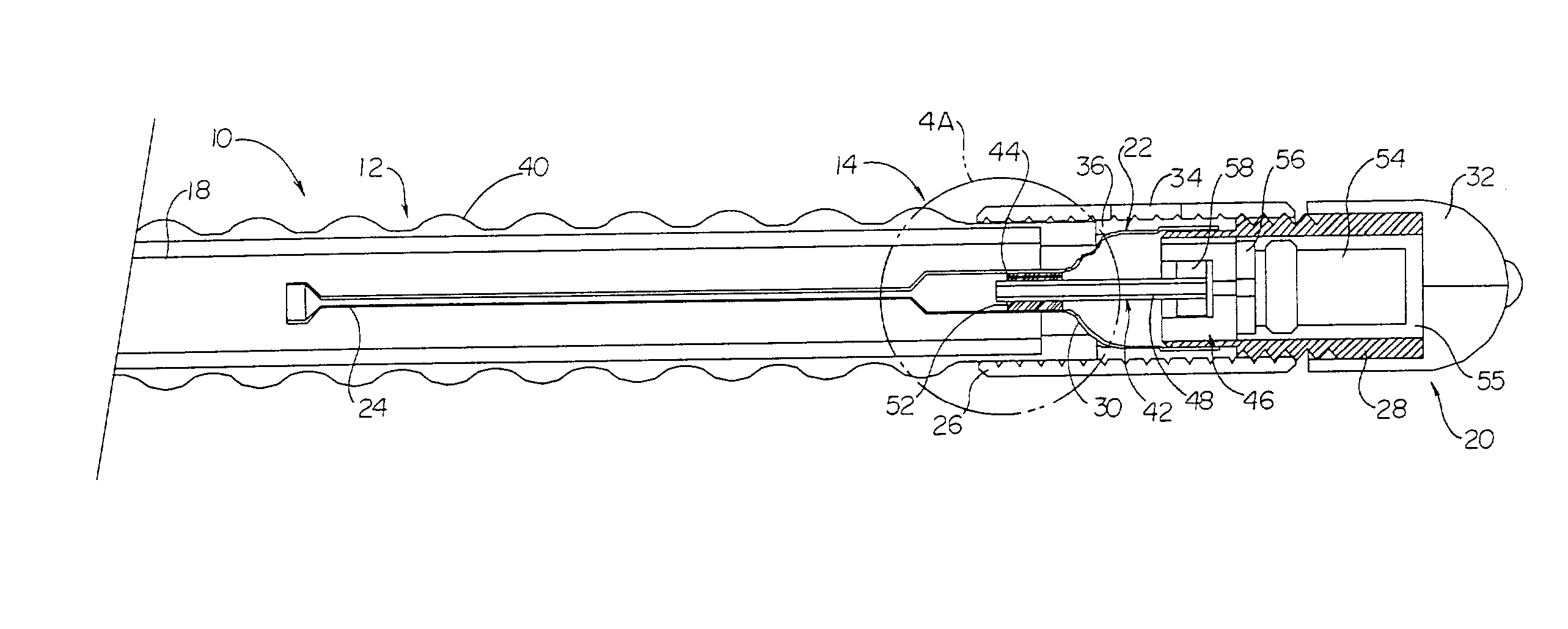
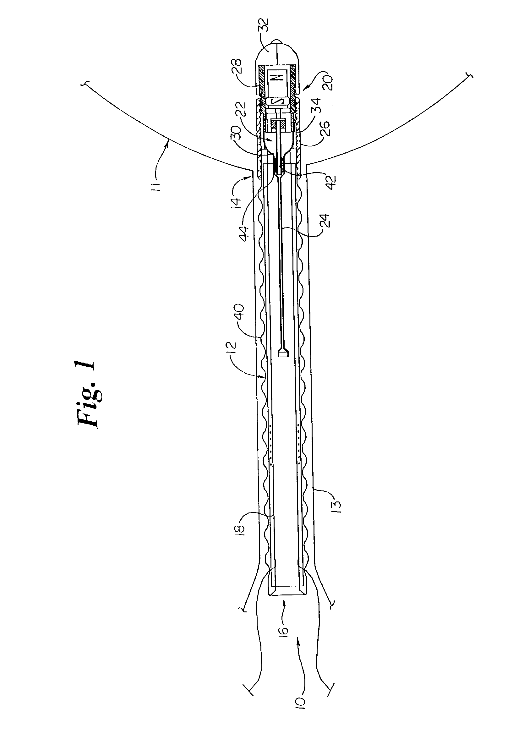
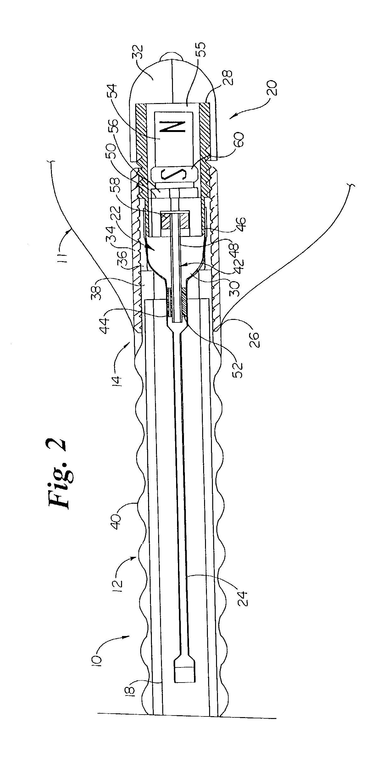
[0032]Generally referencing the figures, more particularly to FIGS. 1 and 2, there is shown a urinary flow control device 10 which generally includes an elongate member 12 having proximal 14 and distal 16 ends and a lumen 18 capable of discharging urine therethrough, and a flow control assembly 20, operatively joined to the elongate member 12, having first 22 and second 24 fluid containing compartments adapted to be in fluid communication with each other. The flow control assembly 20, which is generally adapted to receive and contain urine from the bladder so as to impinge upon the first fluid containing compartment 22, is designed to be responsive to increased bladder pressure such that fluid is displaced from the first fluid containing compartment 22 to the second fluid containing compartment 24. Such responsiveness permits the select passage of urine from the bladder to the lumen 18 of the elongate member 12 for discharge into and through the urethra.

[0033]The urinary flow contro...


PUM


Abstract

A urinary flow control device having a bladder responsive flow control assembly operatively engaged with an elongate member having proximal and distal ends, and a lumen capable of discharging urine therethrough is provided. The flow control assembly includes first and second fluid containing compartments adapted to be in fluid communication. The flow control assembly is adapted to receive and contain urine from a bladder so as to impinge upon the first fluid containing compartment. The flow control assembly is responsive to increased bladder pressure such that fluid is displaced from the first fluid containing compartment to the second fluid containing compartment to thereby permit select passage of received urine to the lumen of the elongate member for discharge therethrough. A method of controlling urinary flow is likewise provided.

Description

[0001]This application is a continuation of Ser. No. 09 / 772,088 filed on Jan. 26, 2001, U.S. Pat. No. 6,527,702, filed under 35 U.S.C. §111(a) claiming priority under 35 U.S.C. §119(e)(1), of provisional application Ser. No. 60 / 179,038, having a filing date of Feb. 01, 2000, filed under 35 U.S.C. §111(b).TECHNICAL FIELD[0002]The present invention generally relates to medical devices, and more particularly to bladder control devices, and still more particularly to an indwelling urinary flow control device for the treatment of urinary incontinence.BACKGROUND OF THE INVENTION[0003]Although a variety of treatment devices and / or methodologies have been developed, urinary incontinence for both men and women remains a persistent problem. Heretofore known approaches to the problem are generally recognized as either remedial or corrective. Remedial approaches (i.e., those primarily dealing with the effects of incontinence) have primarily included the use of catheters in combination with coll...

Claims


Application Information

Patent Timeline
IPC IPC(8): A61F2/02A61F2/00
CPCA61F2/0018A61F2/0022Y10S128/25
Inventor WHALEN, MARK J.WILLARD, LLOYD K.
Owner SRS MEDICAL SYST INC
Why Eureka
Try Eureka