
Wide band antenna for mobile communication

Inactive Publication Date: 2006-02-21
ANTENNA TECH
View PDF10 Cites 1 Cited by
  • Summary
  • Abstract
  • Description
  • Claims
  • Application Information

AI Technical Summary

Benefits of technology

[0015]It is an object of the present invention to provide a mobile communication wide-band antenna for providing wide-band frequency characteristics and enabling a user to distinguish normal radiation states of the antenna with the naked eye.

Problems solved by technology

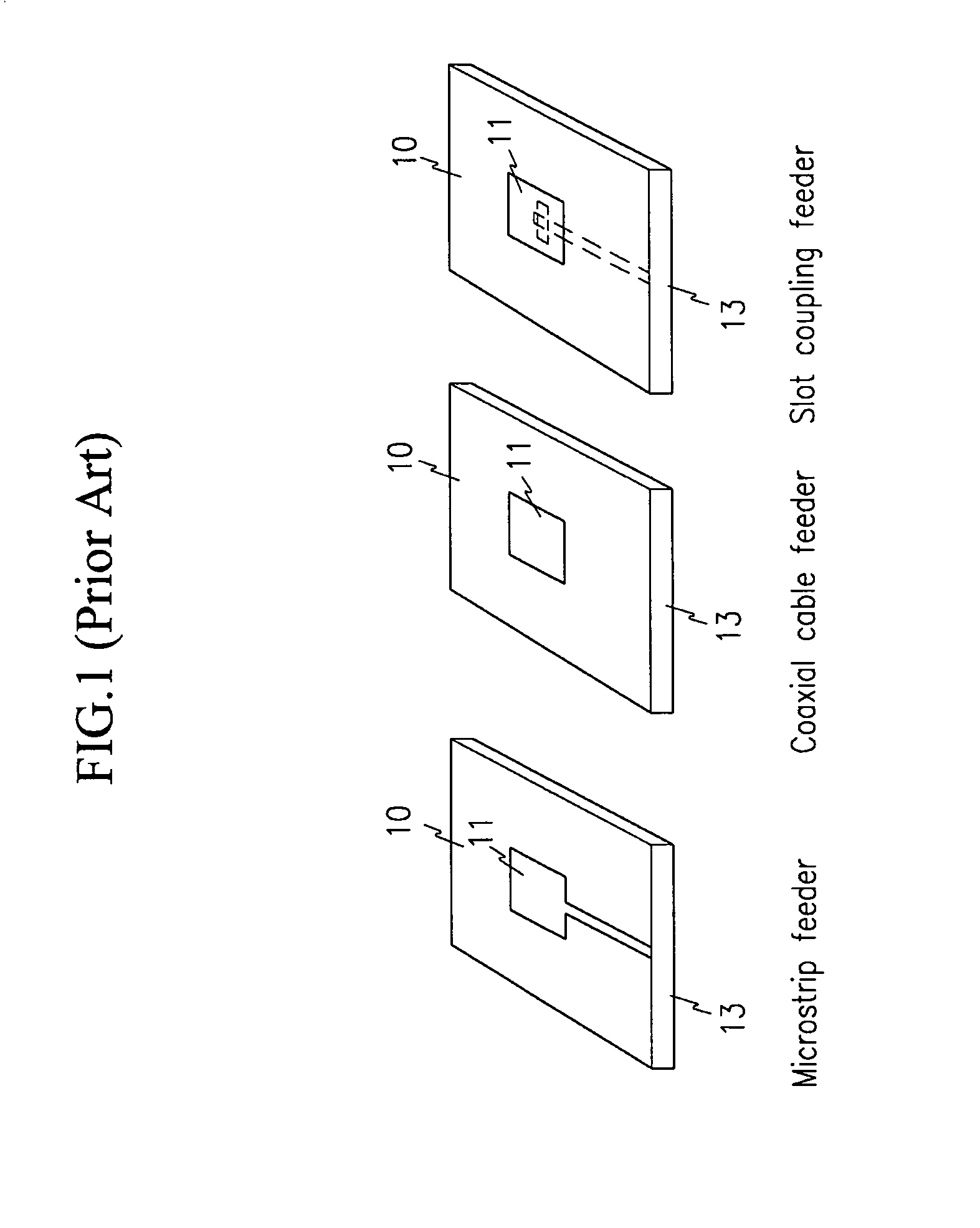
However, the general patch antenna shown in FIG. 1 has a restriction in the case of expanding the frequency bands, and when the dielectric substrate 10 is designed to have low dielectric constant, the design cost is increased because a thick and low dielectric constant substrate 10 generates high-order surface waves.
As described above, because of the bandwidth restriction caused by its structure, the general patch antenna cannot be a common use antenna for supporting various mobile communication services such as cellular phones, PCS and IMT-2000.
Hence, respective antennas corresponding to the various services must be separately installed, and accordingly, this installation spoils the beauty of the interiors of buildings and generates excessive installation and maintenance costs.
In this case, a user cannot determine whether signal power is radiated from the installed patch antennas in the rated manner.
In other words, the user cannot distinguish with the naked eye whether the patch antennas are normally operating.
To check their operating states, the user must either check receipt power while the user is near the antenna using a terminal or measure the same using a spectrum analyzer, thereby causing inconvenience.

Method used


Image

  • Wide band antenna for mobile communication
  • Wide band antenna for mobile communication
  • Wide band antenna for mobile communication

Examples


Embodiment Construction

[0026]In the following detailed description, only the preferred embodiment of the invention has been shown and described, simply by way of illustration of the best mode contemplated by the inventor(s) of carrying out the invention. As will be realized, the invention is capable of modification in various obvious respects, all without departing from the invention. Accordingly, the drawings and description are to be regarded as illustrative in nature, and not restrictive.

[0027]FIG. 3 shows a block diagram of a mobile communication wide-band antenna according to a first preferred embodiment of the present invention.

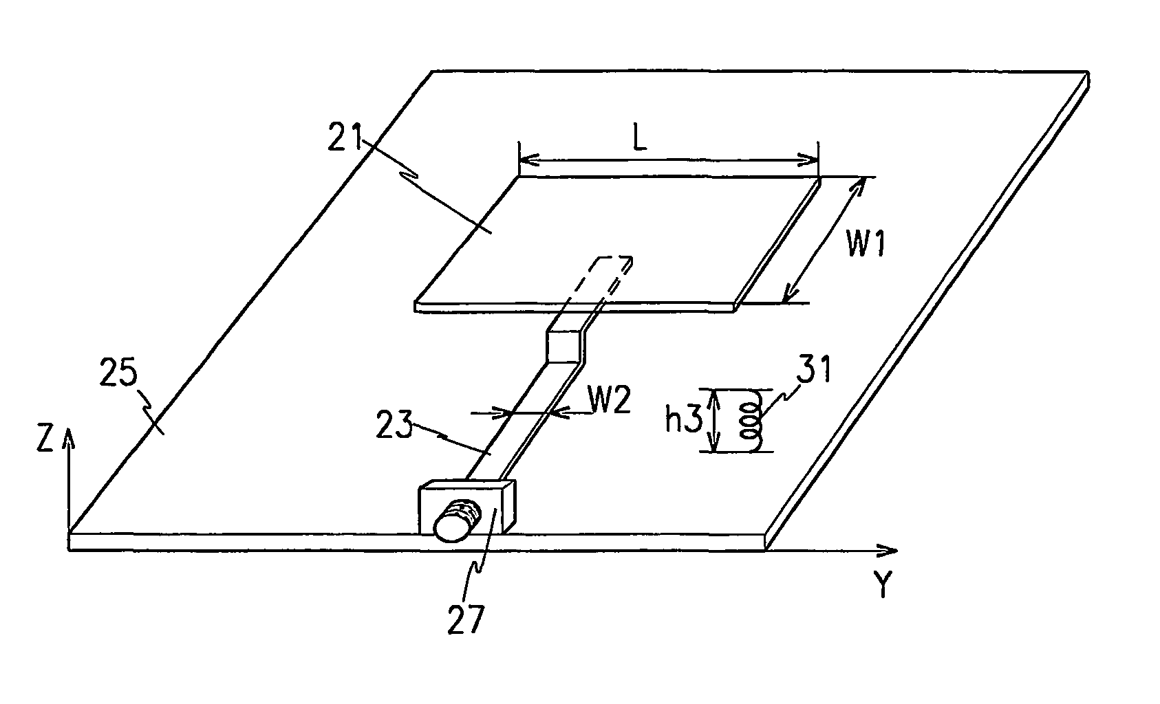
[0028]As shown, the mobile communication wide-band antenna comprises a radio wave radiator 20 for receiving radio frequency (RF) signals and direct current (DC) bias and radiating corresponding radio waves; and an operating state display 30 for receiving the radio waves radiated by the radio wave radiator 20 and displaying operating states of the radio wave radiator 20.

[0029]...


PUM


Abstract

Disclosed is a mobile communication wide band antenna that comprises a radio wave radiator for receiving transmission signals and power and radiating radio waves corresponding to the transmission signals; and an operating state display for receiving the radio waves radiated by the radio wave radiator and displaying operating states of the radio wave radiator according to the received radio waves. The radio wave radiator comprises a ground surface for functioning as ground; a radiation element supported by the ground surface to have a first gap from the ground surface and radiating the radio waves; and a microstrip feeder supported by the ground surface, having a second gap and a third gap from the ground surface, and for receiving the transmission signals and the power and having an electromagnetic coupling with the radiation element, the third gap being provided to be located between the ground surface and the radiation element.

Description

[0001]This application is a 371 of PCT / KR01 / 01644 dated Sep. 28, 2001.BACKGROUND OF THE INVENTION[0002](a) Field of the Invention[0003]The present invention relates to an antenna for mobile communication. More specifically, the present invention relates to a wide band antenna for mobile communication for providing wide band frequency features and enabling a user to easily distinguish normal radiation states of the antenna.[0004](b) Description of the Related Art[0005]Various wireless communication services have become available in fields such as cellular phones and personal communication services (PCS), and the next generation mobile communication system, the IMT-2000 service, will be issued in the near future. Accordingly, more techniques for minimizing and reducing the weight of terminals or base station communication devices have been required.[0006]Recent developments of additional functions such as wireless data communications mean that the conventional communication services h...

Claims


Application Information

Patent Timeline
IPC IPC(8): H01Q1/24H01Q9/04H01Q13/08
CPCH01Q9/0407H01Q9/0457H01Q9/0442H01Q13/08
Inventor BAE, JUNG-BIN
Owner ANTENNA TECH
Learn More