Detection of recorded data employing interpolation with gain compensation

a technology of gain compensation and recorded data, applied in the field of data detection in a communications system, can solve the problems of unfavorable data acquisition, unfavorable data acquisition, and inaccurate reading of servo information by the head,

Active Publication Date: 2006-02-21
AVAGO TECH INT SALES PTE LTD
View PDF11 Cites 80 Cited by
  • Summary
  • Abstract
  • Description
  • Claims
  • Application Information

AI Technical Summary

Problems solved by technology

An imperfect spindle might not allow the disk in the hard drive to spin properly at the disk's center.
If the disk is not rotating at the center, then the track rotating under the head will not follow a circular trajectory, and hence the head might not be able to read the servo information properly.
Even though the disk may spin properly in a different hard disk drive while reading the servo information, since the information was not written properly on a circular track, the head might not be able to read the servo information accurately.
However, for RRO detection, it is not desirable to write a preamble for format efficiency reasons.
Also, detection of the RRO address mark is prone to detection errors because the RRO detector may begin detection in the DC erase field without the proper sampling phase (i.e., there is no preamble to guide the timing loop).
The performance of these detectors degrades significantly when the samples are generated with timing errors.
Since the sampling phase is not known when reading the RRO data field, a Viterbi detector is more prone to making errors.
Variations in signal level, termed gain error, might result in a considerable difference between the ideal peak levels and observed peak levels when the RRO AM is found.
Maximum likelihood detection suffers in performance when ideal peak levels are employed when searching for peaks in the presence of gain errors.

Method used


Image

  • Detection of recorded data employing interpolation with gain compensation
  • Detection of recorded data employing interpolation with gain compensation
  • Detection of recorded data employing interpolation with gain compensation

Examples


Embodiment Construction

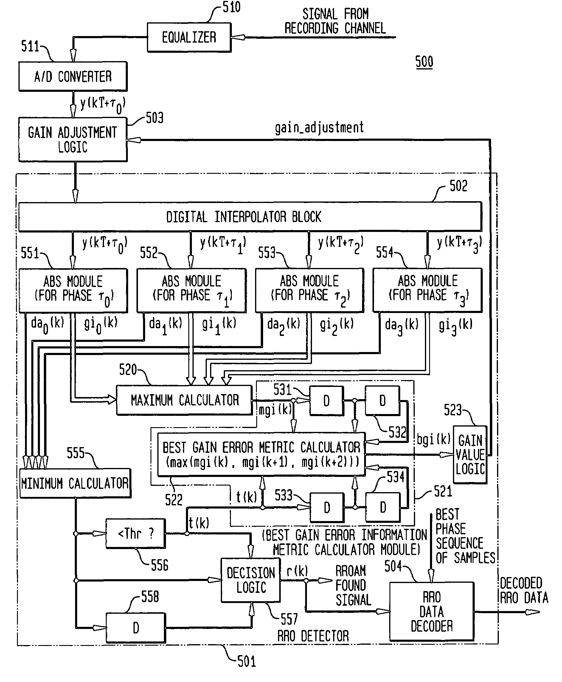
[0034]In accordance with exemplary embodiments of the present invention, a repeatable run out (RRO) detector of a receiver generates a gain adjustment value to compensate for variations in gain of an asynchronously sampled signal including RRO data. The receiver employs interpolation of the asynchronous sample sequence and generates gain estimates for both the asynchronous sample sequence and one or more interpolated sample sequences. The RRO detector selects best phase samples from the asynchronous sample sequence and one or more interpolated sample sequences to detect the RRO data. The RRO detector also generates a gain compensation value from the gain estimates for the best phase samples. Gain compensation values for several RRO data detection events are combined to generate a gain adjustment value. The gain adjustment value is then employed to adjust subsequent asynchronous sample sequences to improve RRO detection performance.

[0035]While the present invention is described for d...


PUM

PropertyMeasurementUnit
distanceaaaaaaaaaa
distance measureaaaaaaaaaa
thresholdaaaaaaaaaa

Abstract

A repeatable run-out (RRO) detector employs one or more digital interpolators to interpolate asynchronous sample values representing an RRO address mark (AM) and RRO data, and an asynchronous maximum-likelihood (AML) detector to detect the RRO AM. The AML detector selects one of either the asynchronous or interpolated sample sequences that are closest in distance to the ideal RRO AM sample sequence. In addition, a gain value is generated for each of the asynchronous and interpolated sample sequences. Once the RRO AM is detected, the AML detector provides a RRO AM found signal. Gain estimate values for either the selected asynchronous or selected interpolated sample sequences corresponding to the RRO AM found signal are averaged over a predefined number of detection events to generate a best gain error metric (BGEM). The BGEM is employed to adjust the gain of the asynchronous sample sequence.

Description

CROSS-REFERENCE TO RELATED APPLICATIONS[0001]This application is related to U.S. patent application Ser. No. 10 / 436,526, filed May 13, 2003 as the teachings of which are incorporated herein by reference.BACKGROUND OF THE INVENTION[0002]1. Field of the Invention[0003]The present invention relates to detection of data in a communications system, and, more particularly, to detection of servo repeatable run out (RRO) information from a channel.[0004]2. Description of the Related Art[0005]A Read channel integrated circuit (IC) is a component of a modem hard disk drive, such as a hard disk drive found in many PCs. A Read channel component converts and encodes data to enable the (e.g., magnetic) recording head(s) to write data to the disk and then read back the data accurately. The disks in a hard disk drive typically include many tracks containing encoded data, and each track comprises one or more of user (or “read”) data sectors as well as “servo” data sectors embedded between the read s...

Claims


Application Information

Patent Timeline
Patent Type & Authority Patents(United States)
IPC IPC(8): G11B20/10G11B5/596
CPCG11B5/59627G11B20/10027G11B20/10009G11B20/1876
Inventor ANNAMPEDU, VISWANATHAZIZ, PERVEZ M.
Owner AVAGO TECH INT SALES PTE LTD
Why Eureka
Try Eureka