Communication terminal device and channel estimating method

a terminal device and channel estimation technology, applied in multiplex communication, wireless communication, baseband system details, etc., can solve the problem of reducing the reliability of channel estimation values compared to a case of transmission diversity, and achieve the effect of improving the reliability of channel estimation values

Inactive Publication Date: 2006-02-21
PANASONIC CORP
View PDF15 Cites 47 Cited by
  • Summary
  • Abstract
  • Description
  • Claims
  • Application Information

AI Technical Summary

Benefits of technology

[0023]It is an object of the present invention to provide a communication terminal apparatus and channel estimation method in

Problems solved by technology

However, when the base station rotates the phase of the individual channel signals for every slot as appropriate, the reception slots at the communication terminal become discontiguous, and therefore the conventional communica

Method used


Image

  • Communication terminal device and channel estimating method
  • Communication terminal device and channel estimating method
  • Communication terminal device and channel estimating method

Examples


embodiment 1

[0045]Embodiment 1 will describe a case where the base station transmits individual channel signal A and individual channel signal B without changing their amplitudes.

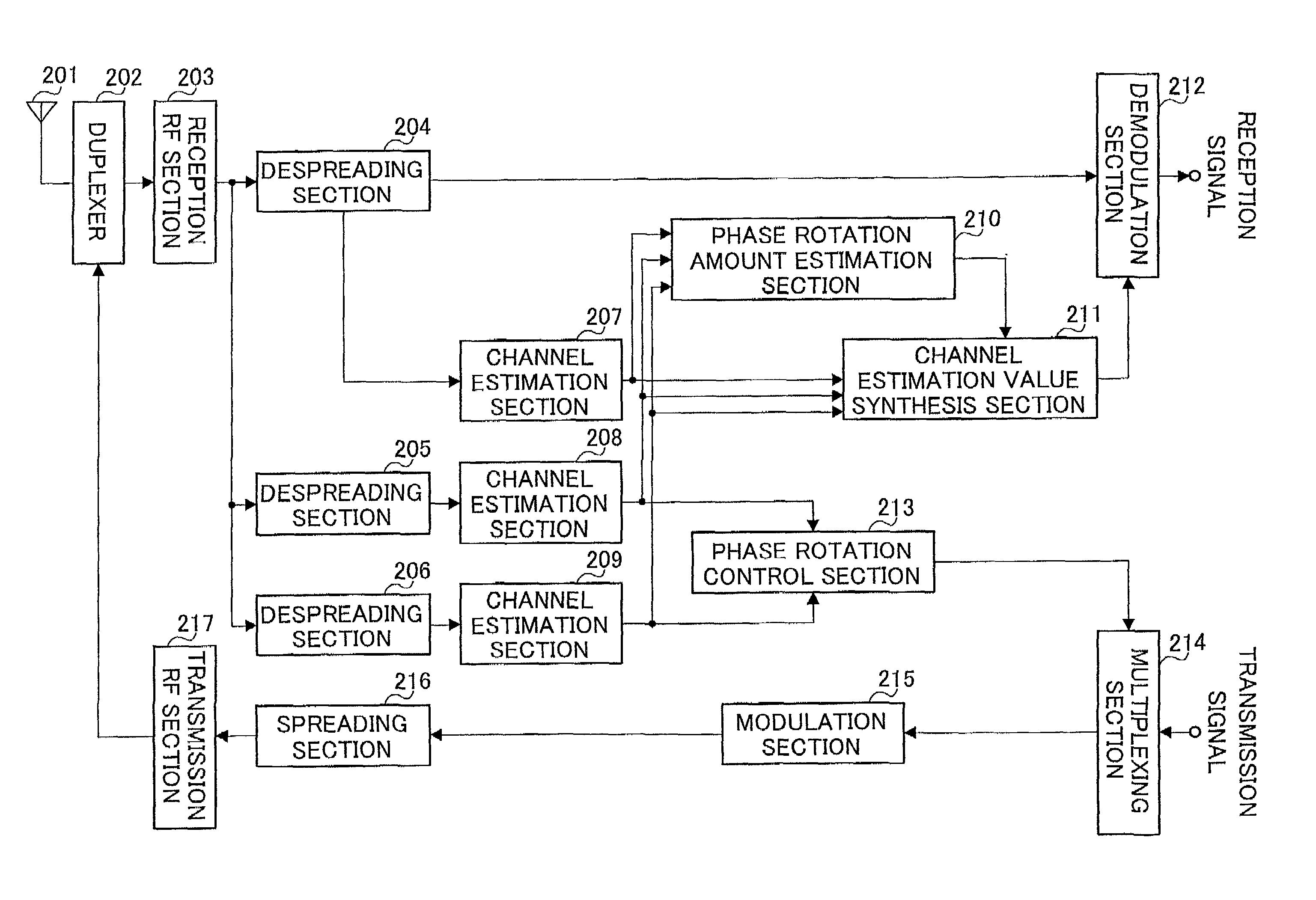
[0046]FIG. 5 is a block diagram showing a configuration of a communication terminal according to Embodiment 1 of the present invention.

[0047]In the communication terminal shown in FIG. 5, antenna 201 receives a signal transmitted from the base station and sends a signal to the base station. Duplexer 202 switches between time zones of transmission and reception. Reception RF section 203 amplifies the reception signal that passes duplexer 202 and converts the frequency of the reception signal to a baseband signal.

[0048]Despreading section 204 despreads the output signal of reception RF section 203 with a spreading code of an individual channel signal and extracts a modulated signal of the individual channel signal. Likewise, despreading section 205 despreads the output signal of reception RF section 203 with a spreading ...

embodiment 2

[0079]Embodiment 2 will describe a case where the base station carries out transmission by changing the amplitudes of individual channel signal A and individual channel signal B.

[0080]The relationship of channel estimation values in this embodiment will be explained using FIG. 7.

[0081]Suppose the base station sets the amplitude of individual channel signal B “a” times (hereinafter this “a” will be referred to as “amplitude coefficient”) the amplitude of individual channel signal A. When the amplitude ratio of αa(n) to βa(n) is assumed to be k, the amplitude ratio of αb(n) to βb(n) is (k×a).

[0082]In this case, as shown in FIG. 7, channel estimation value β(n) of an individual channel signal and synthesis value α(n) of common pilot channel signal A and common pilot channel signal B do not point in the same direction.

[0083]Thus, when the base station carries out transmission by changing the amplitudes of individual channel signal A and individual channel signal B, α(n) cannot be used a...

embodiment 3

[0091]When a maximum Doppler frequency of fading is low and a fading variation is moderate, it is possible to improve the reliability of channel estimation values by averaging fading estimation values over a plurality of reception slots.

[0092]However, as described above, when transmission diversity is introduced to a radio communication system, reception slots become discontiguous, and therefore it is not possible to average channel estimation values over a plurality of slots.

[0093]Embodiment 3 is intended to solve this problem and describes a case where transmission diversity is introduced and channel estimation values are synthesized over a plurality of slots.

[0094]FIG. 9 is a block diagram showing a configuration of a communication terminal according to Embodiment 3 of the present invention. In the communication terminal shown in FIG. 9, the same components as those in the communication terminal in FIG. 5 will be assigned the same reference numerals as those in FIG. 5 and explana...


PUM


Abstract

A phase rotation amount estimating unit (210) rotates a channel estimation value of a signal in a common pilot channel (B) through a candidate phase rotation amount θ (θ=0, 180) for synthesizing with a channel estimation value of a signal in a common pilot channel (A). A phase rotation is estimated based on the highest one of orthogonalities between this synthesis result and channel estimation values of signals in individual channels. A channel estimation value synthesis unit (211) synthesizes a value obtained by rotating a channel estimation value of a signal in the common pilot channel (B) through a phase rotation amount θ with a channel estimation value of a signal in the common pilot channel (A), whereby the reliability of a channel estimation value can be enhanced in a transmission diversity-introduced radio communication system.

Description

TECHNICAL FIELD[0001]The present invention relates to a CDMA-based communication terminal apparatus and channel estimation method used in a radio communication system such as automobile telephone and cellular telephone.BACKGROUND ART[0002]In a radio communication system, transmission diversity may be used on the base station side in order to increase reception power of transmission signals of individual channels (hereinafter referred to as “individual channel signals”) on the communication terminal side by sending individual channel signals to one communication terminal from a plurality of diversity antennas.[0003]FIG. 1 is a system configuration diagram of a system disclosed in the 3GPP WG1 TSG-RAN WG1 R1-99832 (Physical channels and mapping of transport channels onto physical channels (FDD)), as one example of a radio communication system using transmission diversity.[0004]As shown in FIG. 1, base station 1 transmits common pilot channel transmission signal (hereinafter referred t...

Claims


Application Information

Patent Timeline
IPC IPC(8): H04B7/216H01Q3/24H04B1/712H04B7/06H04B7/08H04B7/26H04J13/00H04L25/02H04L27/00H04W16/28
CPCH04B7/06H04B7/0615H04L25/0214H04L25/0204H04L2027/0022H04B7/02
Inventor HIRAMATSU, KATSUHIKO
Owner PANASONIC CORP
Why Eureka
Try Eureka