Image forming apparatus and process cartridge

a technology of image forming apparatus and process cartridge, which is applied in the field of electrographic image forming apparatus, can solve the problems of abnormal picture development, impediment to the ability of the combination sweep/charging roller b>2/b> to transfer electrical charges, and various problems, so as to reduce toner scatter, ensure the effect of electrical charge application and convenient installation and removal

Inactive Publication Date: 2006-02-21
RICOH KK
View PDF23 Cites 13 Cited by
  • Summary
  • Abstract
  • Description
  • Claims
  • Application Information

AI Technical Summary

Benefits of technology

[0011]The present invention has been developed in order to solve at least the above-mentioned problems. It is an object of the present invention to provide an image forming apparatus and a process cartridge that reduces toner scatter and more evenly and reliably applies an electric charge to an image carrier. It is another object of the present invention to provide a process cartridge that is easy to install and remove. It is another objective of the present invention to provide for miniaturization for desk-top and other uses.

Problems solved by technology

However, when diffusing, loosened toner can also scatter from the combination sweep / charging roller 2 for a great distance.
Scattered toner can then adhere to other surfaces causing various problems and malfunctions, to include abnormal pictures.
In addition, the loosened toner can adhere to the brushes of the combination sweep / charging roller 2, thereby impeding the ability of the combination sweep / charging roller 2 to transfer an electrical charge to the image carrier 1.
For example, uneven charging is possible which will lead to uneven density of toner on the image carrier 1 which, in turn will lead to abnormal picture development.
However, this construction results in largely unusable space being left under this configuration and, thus, is not optimized for miniaturization for desktop use.
Furthermore, this prior application does not teach a removable toner container separate from a removable process cartridge.
Thus, the cartridges must be replaced or recycled when the toner is depleted, which is typically sooner than when the mechanical components of the cartridges are worn out, thus increasing operational costs.

Method used


Image

  • Image forming apparatus and process cartridge
  • Image forming apparatus and process cartridge
  • Image forming apparatus and process cartridge

Examples


Embodiment Construction

[0021]A printer using elect-graph system as the image forming apparatus (“a printer” is merely said as follows) of the present invention will be explained below with reference to the accompanying drawings. This printer consists of four colors toner such as yellow (Y), cyan (C.), magenta (M), and black (K).

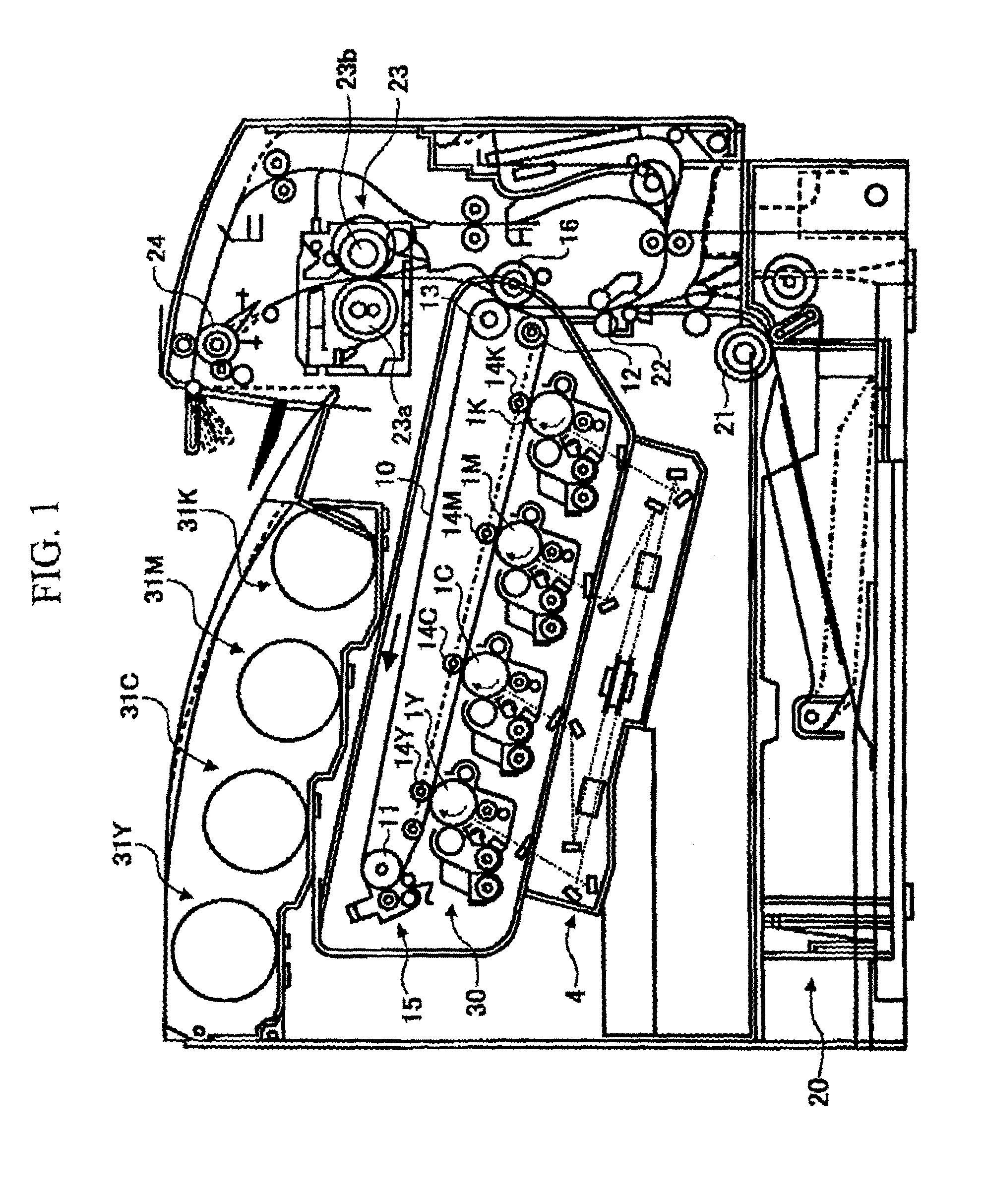
[0022]FIG. 1 shows a figure of outline constitution of a printer related to a present embodiment. This printer comprises four photoreceptor drums 1Y, 1C, 1M, and 1K which are a latent image carrier as an image carrier. (In the figure, a drum-shaped photoreceptor is shown for example, but a belt-shaped photoreceptor can also be used.) Each photoreceptor 1Y, 1C, 1M, and 1K are touching transfer belt 10 as no edge transfer members configured for surface transfer. Each is driven in a direction of mark in the figure.

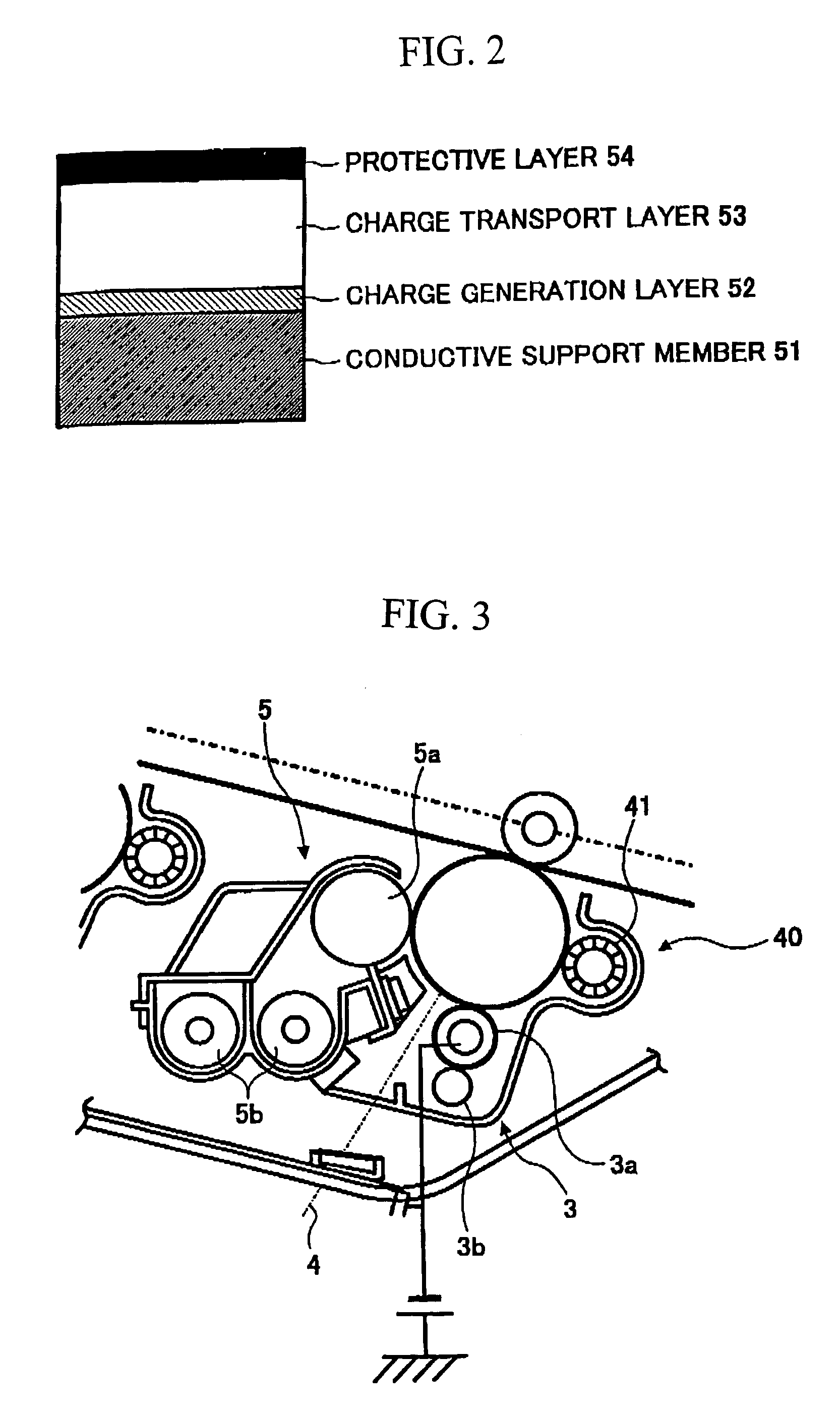
[0023]Each photoreceptor drum 1Y, 1C, 1M, 1K, has the structure that the exposure layer is composed above a cylindrical electroconductivity body which is a comparatively thi...


PUM


Abstract

An image forming process and apparatus, the apparatus including a toner container, a transfer belt below the toner container, a process cartridge below the transfer belt, and an imaging device below the process cartridge. The process cartridge includes a rotating image carrier having an image carrier surface, a brush roller in contact with the image carrier surface, a charging member in contact with the image carrier surface and configured to transfer a charge to the image carrier surface, and a casing including a miler in contact with the image carrier surface and arranged to separate the brush roller from the charging member.

Description

CROSS REFERENCE TO RELATED APPLICATIONS[0001]This application claims priority to Japanese Patent Publication 2002-27463 filed on Sep. 19, 2003, the entire contents of which are incorporated by reference.BACKGROUND OF THE INVENTION[0002]1. Field of the Invention[0003]The present invention relates to an elect-photographic image forming apparatus, to include a printer or a facsimile device, and a corresponding process cartridge.[0004]2. Description of the Related Art[0005]In conventional image forming apparatuses, use of a diffusion means, such as a sweep roller, to loosen toner from an image carrier is known. Typically, the sweep roller is kept in constant contact with the image carrier. Such diffusion means are installed with various kinds of objects.[0006]One purpose of the sweep roller is to loosen toner adhered to the image carrier so that toner may be easily collected and recycled by a toner dispenser device. An advantage of a sweep roller is that it is not necessary to install a...

Claims


Application Information

Patent Timeline
Patent Type & Authority Patents(United States)
IPC IPC(8): G03G21/00G03G9/08G03G15/08G03G15/30G03G21/18
CPCG03G21/0035G03G21/1814G03G2215/0132G03G2221/183G03G2221/1648
Inventor KAWASUMI, MASANORIUMEMURA, KAZUHIKONARUMI, SATOSHIHOSOKAWA, HIROSHIRYUTA, TAKEICHITSUDA, KIYONORIARAI, YUJI
Owner RICOH KK
Why Eureka
Try Eureka