Predictive failure analysis and failure isolation using current sensing

a technology of current sensing and failure analysis, applied in the direction of instruments, nuclear elements, digital computer details, etc., to achieve the effect of less down time for the system

Inactive Publication Date: 2006-02-21
UNILOC 2017 LLC
View PDF17 Cites 23 Cited by
  • Summary
  • Abstract
  • Description
  • Claims
  • Application Information

AI Technical Summary

Benefits of technology

[0005]The present invention addresses the above-mentioned limitations of traditional methods of maintaining and debugging electronic devices by providing preemptive failure prediction and failure isolation using current sensing. The present invention monitors the current signature of devices and warns of a pending failure when the current draw changes above or below a pass range. With the invention, a function can be replaced before the failure occurs, thus providing less down time for the system. The current information can further be used to help isolate failed components once a failure has occurred. For example, if a failure occurs which could involve three different assemblies, the system management could determine that one device has deviated from normal current demands. This increases the likelihood that the device with the deviated current demands is causing the failure.

Problems solved by technology

This increases the likelihood that the device with the deviated current demands is causing the failure.

Method used


Image

  • Predictive failure analysis and failure isolation using current sensing
  • Predictive failure analysis and failure isolation using current sensing
  • Predictive failure analysis and failure isolation using current sensing

Examples


Embodiment Construction

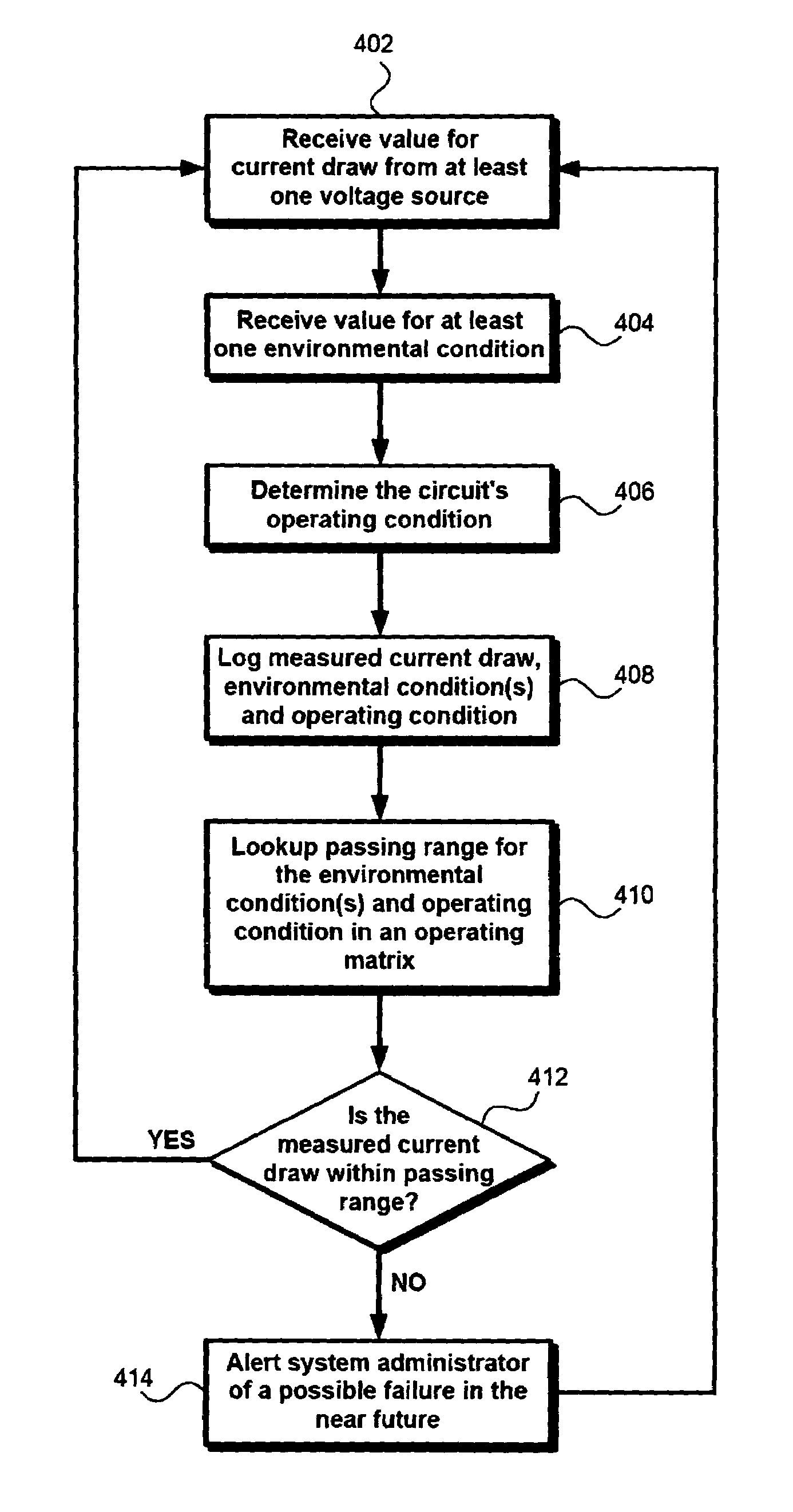
[0015]The following description details how the present invention is beneficially employed to preemptively alert administrators of an impending failure of electronic circuits and to help troubleshoot failed devices. Throughout the description of the invention reference is made to FIGS. 1–3. When referring to the figures, like structures and elements shown throughout are indicated with like reference numerals.

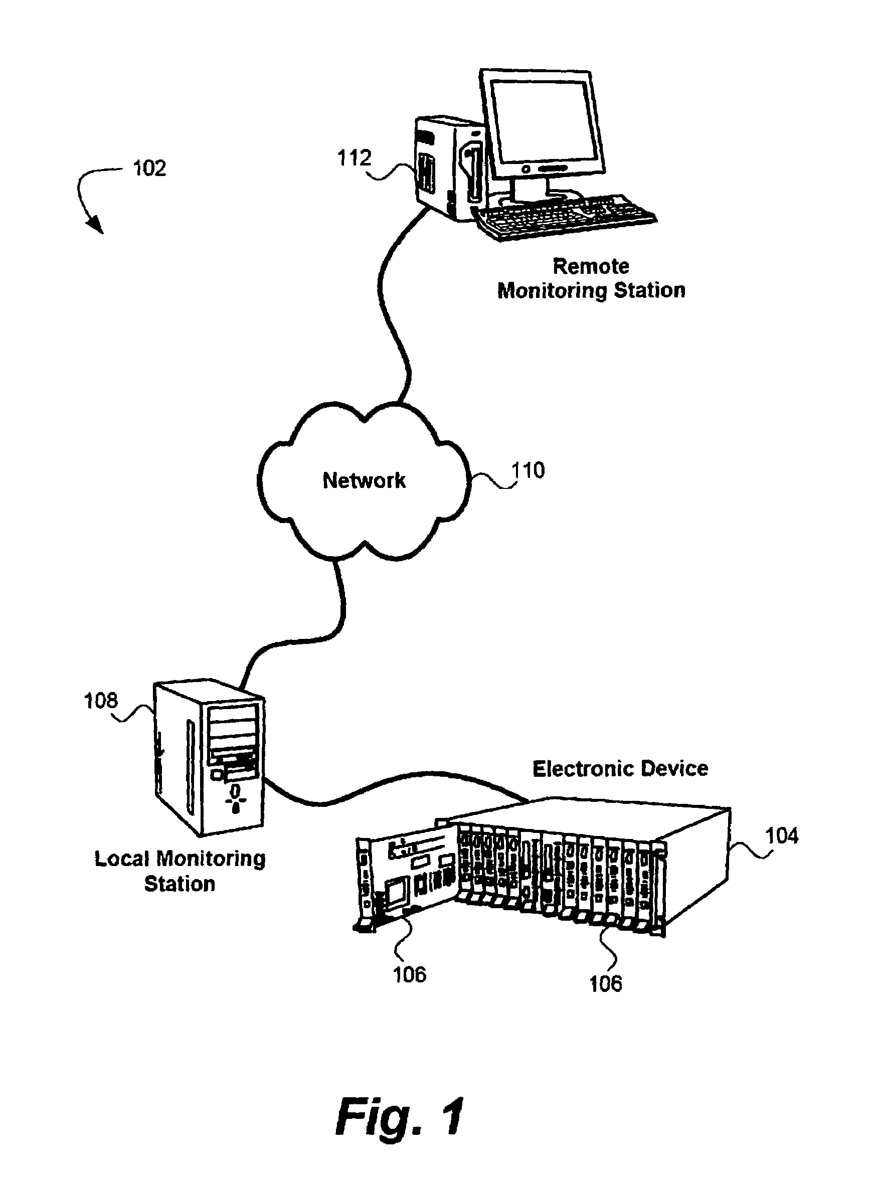
[0016]FIG. 1 shows an exemplary system environment 102 implementing the present invention. It should be noted the environment 102 is presented for illustration purposes only and is representative of countless configurations in which the invention may be implemented. Thus, the present invention should not be considered limited to the system configuration shown in the figure.

[0017]The environment 102 includes an electronic device 104 with a plurality of electronic circuits 106 (also referred to as “cards” or “blades” in some devices). The electronic device 104 may be, for example,...


PUM


Abstract

A method, system, and computer program for predicting the failure of an electronic circuit. One embodiment of the invention monitors the current utilization, environment conditions, and operating conditions of the electronic circuit. A system manager is altered if the current utilization of the electronic circuit is outside a pass range at the measured environmental conditions and the measured operating conditions of the electronic circuit. The invention may also be configured such that if the electronic circuit fails, the electronic circuit is isolated from among a plurality of potentially failed electronic circuits using the measured current utilization, environment conditions, and operating conditions of the electronic circuit.

Description

FIELD OF THE INVENTION[0001]The present invention relates generally to predicting and isolating circuit failures, and more specifically to using supply current measurements in conjunction with operating condition measurements to predict and isolate circuit failures.BACKGROUND[0002]When an electronic device fails there is typically a cost associated in restoring the device's function. In some electronic systems, the cost of a device failure may be nominal, such as the cost of replacing an inexpensive component. In other systems, however, a device failure can be disastrous, causing lost revenue, lost data, and even personal injury. Consider, for example, an electronic device linking two high-speed communication lines together. If the device fails, the connection between the two lines may break and millions of dollars in revenue may be lost while the problem is located and fixed.[0003]Although there is no way of making electronic devices fail proof, there are solutions in the art for m...

Claims


Application Information

Patent Timeline
Patent Type & Authority Patents(United States)
IPC IPC(8): G01R21/00G06F1/26G06F11/24
CPCG06F11/24
Inventor HEPNER, DAVID F.WALLS, ANDREW D.
Owner UNILOC 2017 LLC
Why Eureka
Try Eureka