Die cushion apparatus for hot stretch-forming

a technology of die cushion and hot stretch, which is applied in the direction of woodworking apparatus, drying machines with progressive movements, drying machines, etc., can solve the problems of inoperability of the die cushion assembly, binding of the guidance cylinder, and the temperature difference between the upper and lower plates of the die cushion, so as to prevent the binding of the plurality of guidance devices and prevent the binding of the guide post

Active Publication Date: 2006-02-28
GM GLOBAL TECH OPERATIONS LLC
View PDF3 Cites 44 Cited by
  • Summary
  • Abstract
  • Description
  • Claims
  • Application Information

AI Technical Summary

Benefits of technology

[0008]The improved die cushion assembly of the present invention includes improved guidance devices that are laterally translatably mounted between plates of the die cushion assembly and that are strategically positioned within the die cushion assembly. The improved guidance devices are positioned along the side of the upper and lower plates of the die cushion assembly instead of at the corners thereof. The improved guidance devices also includes mounting structure that permits lateral displacement of the guidance devices without binding thereof. Accordingly, the present invention accommodates differences in thermal expansion of the plates and thereby maintains precise location and alignment between the plates.
[0010]According to a first aspect of the present invention, there is provided a die cushion apparatus for use in a stretch-forming process involving heated tooling. The die cushion apparatus includes a lower plate, an upper plate that undergoes different thermal expansion than the lower plate, and guidance devices mounted between the upper and lower plates. The guidance devices include a guide post, a bearing sleeve circumscribing at least a portion of the guide post, and a cylinder circumscribing at least a portion of the bearing sleeve. One of the guide post or cylinder is mounted in fixed relation to one of the upper and lower plates, and the other of the guide post or the cylinder is mounted in laterally translatable relation to the other of the upper and lower plates to accommodate lateral relative displacement between the upper and lower plates due to different thermal expansion thereof, thereby preventing binding of the plurality of guidance devices.
[0011]According to a second aspect of the present invention, there is provided a guidance device for mounting between upper and lower plates of a die cushion apparatus for a hot stretch-forming process, wherein the upper plate undergoes different thermal expansion than the lower plate. The guidance device includes a guide post, a bearing sleeve circumscribing the guide post, and a cylinder circumscribing the bearing sleeve. One of the guide post and the cylinder is mounted in fixed relation to one of the upper and lower plates, and the other of the guide post and the cylinder is mounted in laterally translatable relation to the other of the upper and lower plates to accommodate lateral relative displacement between the upper and lower plates due to different thermal expansion thereof, thereby preventing binding of the guide post within the cylinder.

Problems solved by technology

The electrical heating elements primarily heat the male and female tooling, but also tend to incidentally heat the upper and lower plates of the die cushion assembly.
Unfortunately, however, the temperatures of the upper plate and the lower plate of the die cushion tend to be significantly different due to differences in the heat generated by the electrical resistance heating elements or by differences in residual heat generated during the forming process.
In other words, the upper plate tends to expand outwardly to a greater degree than the lower plate, and the upper plate thereby urges the upper end of the guidance cylinders in a direction laterally away from the lower end of the guidance cylinders, thereby leading to binding of the guidance cylinders and inoperability of the die cushion assembly.

Method used


Image

  • Die cushion apparatus for hot stretch-forming
  • Die cushion apparatus for hot stretch-forming
  • Die cushion apparatus for hot stretch-forming

Examples


Embodiment Construction

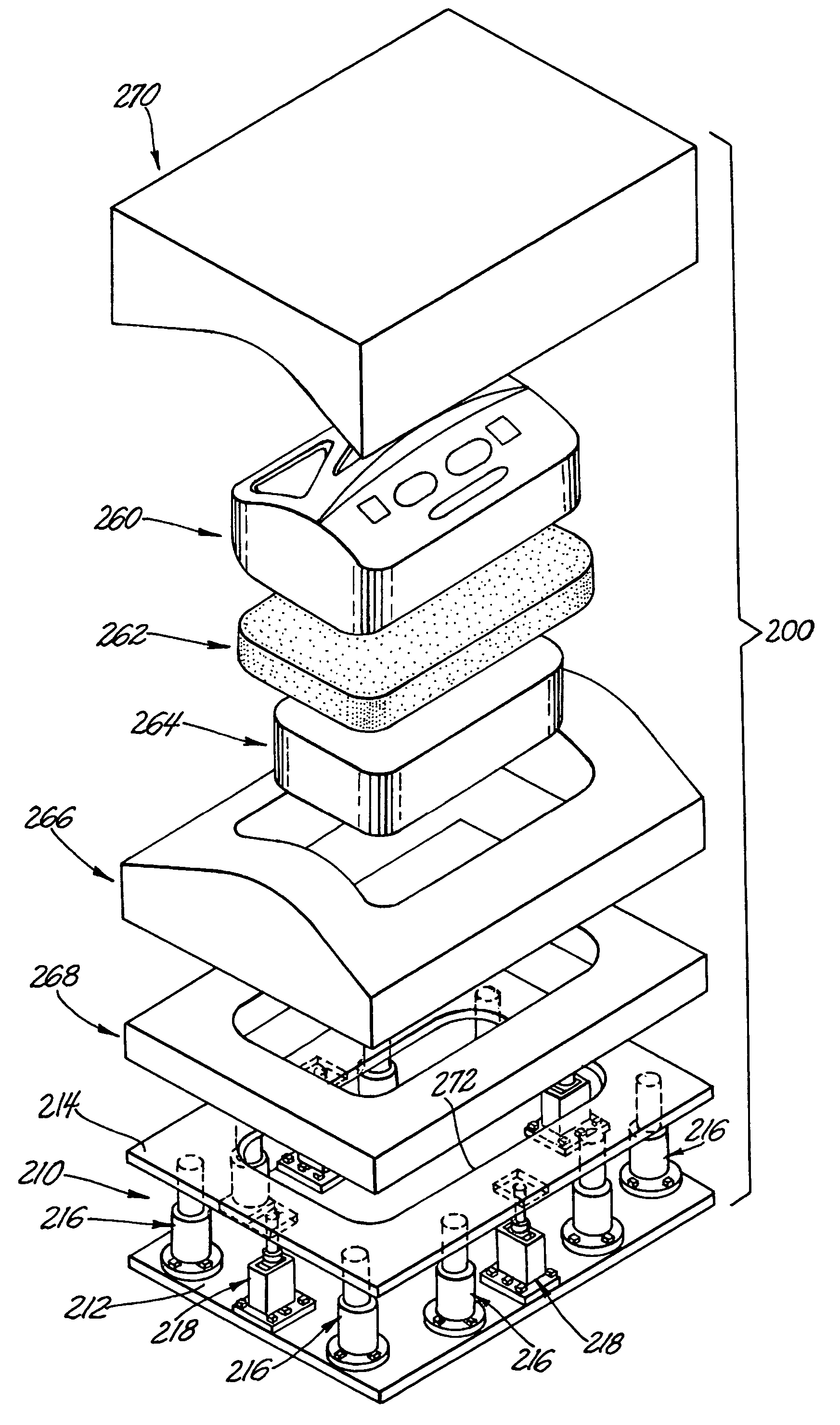
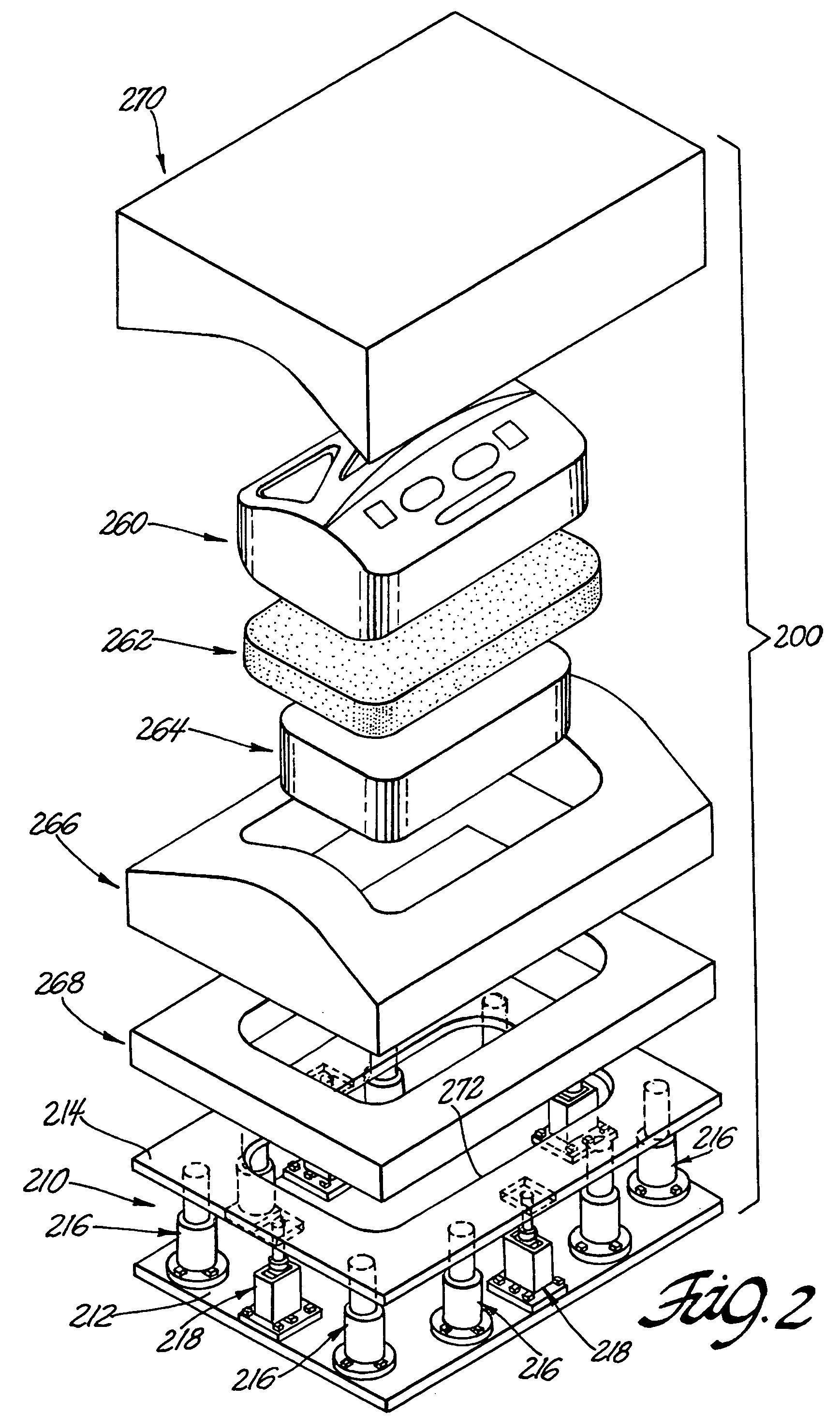
[0022]The present invention has application in hot stretch-forming processes, particularly those processes capable of producing articles of complex shape, such as automotive body panels. More particularly, the present invention is directed to such hot stretch-forming processes that use a self-contained die cushion or extraction apparatus.

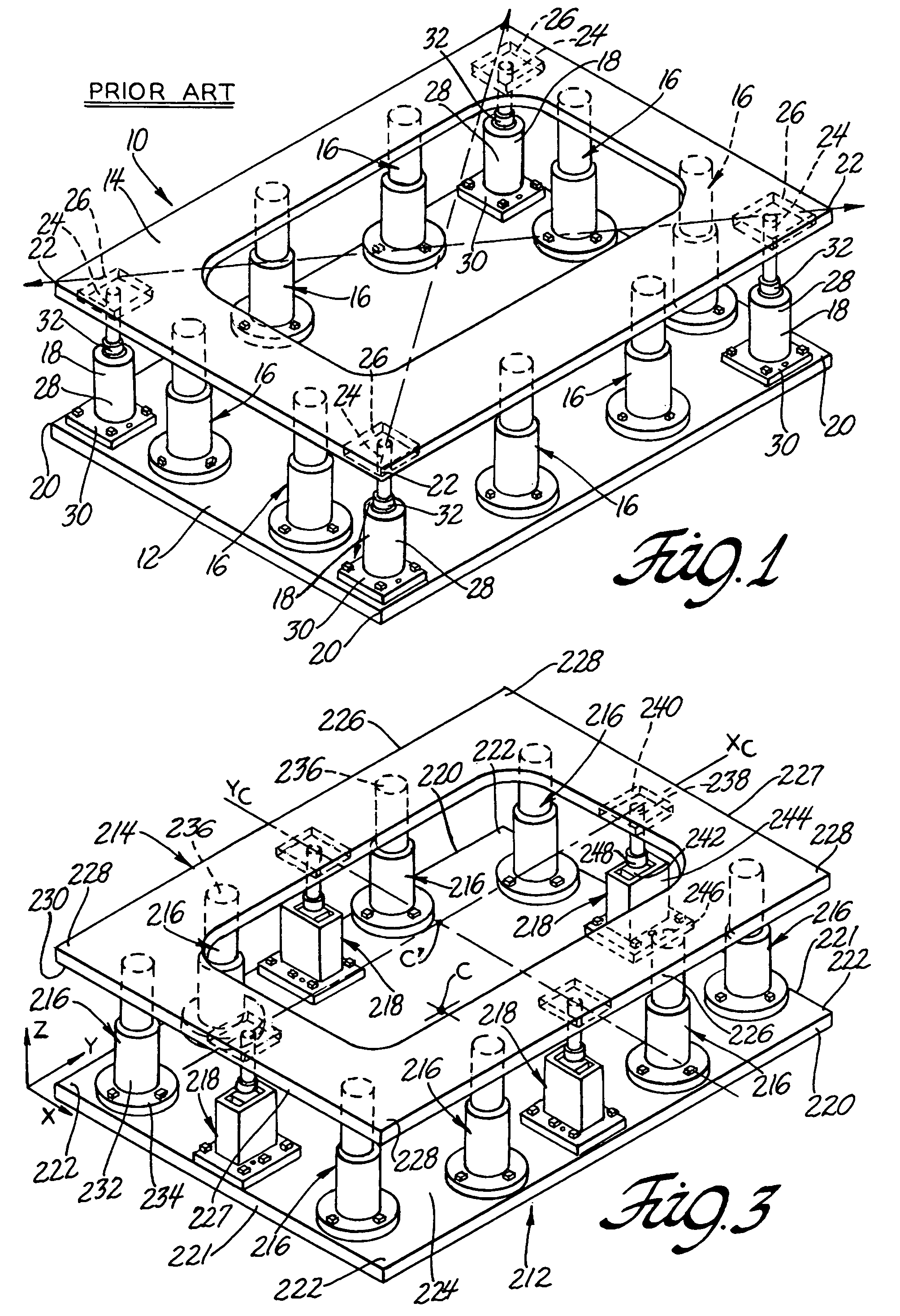
[0023]FIG. 1 illustrates a die cushion assembly 10 according to the prior art. The die cushion assembly 10 includes a lower plate 12, an upper plate 14, and a plurality of cushion devices 16 and guidance devices 18 fixedly mounted therebetween. The cushion devices 16 are positioned in the margins of the upper and lower plates 12, 14 along the sides thereof, laterally between the guidance devices 18. The guidance devices 18, however, are immovably fixed at positions between respective lower and upper corners 20, 22 of the lower and upper plates 12, 14 for maintaining alignment of the upper plate 14 with respect to the lower plate 12. The guidance dev...


PUM

PropertyMeasurementUnit
pressureaaaaaaaaaa
forming temperaturesaaaaaaaaaa
tensile elongationsaaaaaaaaaa

Abstract

A self-contained die cushion assembly for use in a stretch-forming process involving heated tooling. A lower plate is mounted below an upper plate that undergoes different thermal expansion than the lower plate. Guidance devices are mounted between the upper and lower plates and include a guide post, a bearing sleeve circumscribing the guide post, and a cylinder circumscribing the bearing sleeve. The guide post is mounted in fixed relation to the upper plate, and the cylinder is mounted in laterally translatable relation to the lower plate to accommodate lateral relative displacement between the upper and lower plates due to different thermal expansion thereof, thereby preventing binding of the guidance devices.

Description

TECHNICAL FIELD[0001]This invention pertains to apparatus for metal deforming. More specifically, this invention pertains to a self-contained die cushion assembly for use with hot stretch-forming operations such as super-plastic-forming (SPF) or quick-plastic-forming (QPF) processes.BACKGROUND OF THE INVENTION[0002]In conventional stamping processes, it is often desirable to hold a blank sheet of metal about its peripheral margin during forming of a stamped component. In such processes, it is known to provide a female form die mounted to a movable upper platen of a press, a male form punch fixedly mounted to a fixed lower platen of the press, and a binder ring displaceably mounted to the press. The binder ring encircles the form punch and is positioned vertically flush with respect thereto, such that the blank sheet of metal can be laid flat across the binder ring and the form punch. In operation, the upper platen strokes downwardly, wherein the form die pinches the peripheral margi...

Claims


Application Information

Patent Timeline
Patent Type & Authority Patents(United States)
IPC IPC(8): B21J9/18B21D26/02
CPCB21D26/055Y10T29/4984Y10S384/905
Inventor KRUGER, GARY A.KONOPNICKI, MARK G.HAMMAR, RICHARD HARRY
Owner GM GLOBAL TECH OPERATIONS LLC
Why Eureka
Try Eureka